4.
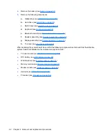
Remove the battery (see
Battery on page 51
).
5.
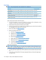
Remove the following components:
a.
Optical drive (see
Optical drive on page 54
)
b.
Hard drive (see
Hard drive on page 56
)
c.
Switch cover (see
Switch cover on page 66
)
d.
Keyboard (see
Keyboard on page 68
)
e.
Bluetooth module (see
Bluetooth module on page 71
)
f.
Speaker assembly (see
Speaker assembly on page 72
)
g.
Display assembly (see
Display assembly on page 73
)
h.
Top cover (see
Top cover on page 82
)
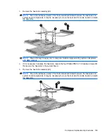
When replacing the system board, be sure that the following components are removed from the defective
system board and installed on the replacement system board:
●
TV tuner module (see
TV tuner module on page 58
)
●
RTC battery (see
RTC battery on page 60
)
●
WLAN module (see
WLAN module on page 61
)
●
Memory module (see
Memory module on page 64
)
●
Modem module (see
Modem module on page 90
)
●
Heat sink (see
Heat sink on page 102
)
●
Processor (see
Processor on page 106
)
92
Chapter 4 Removal and replacement procedures
Содержание Pavilion dv7-1100 - Entertainment Notebook PC
Страница 1: ...HP Pavilion dv7 Entertainment PC Maintenance and Service Guide ...
Страница 4: ...iv Safety warning notice ...
Страница 26: ...Computer major components 18 Chapter 3 Illustrated parts catalog ...
Страница 113: ...Reverse this procedure to install the heat sink Component replacement procedures 105 ...
Страница 142: ...Where used 2 screws that secure the modem module to the system board 134 Chapter 7 Screw listing ...
Страница 153: ...Where used 6 screws that secure the top cover to the base enclosure Phillips PM2 5 6 0 screw 145 ...
Страница 167: ...Universal Serial Bus Pin Signal 1 5 VDC 2 Data 3 Data 4 Ground Universal Serial Bus 159 ...
Страница 181: ......


