background image

5-3

Compaq Professional Workstation 6000 and 8000 Reference Guide

Writer: Jean Schuck   Project: Compaq Professional Workstation 6000 and 8000 Reference Guide   Comments: 270217-002

File Name: F-CH05.DOC   Last Saved On: 11/3/97 4:32 PM

COMPAQ CONFIDENTIAL - NEED TO KNOW REQUIRED

Connecting to an Ethernet Cable

Two types of network connectors are included on your workstation. Each type
requires different equipment and installation procedures, as explained in the
following sections.

IMPORTANT:

     To avoid configuration problems, do not attempt to utilize the

RJ-45 and AUI connectors simultaneously.

Attaching a Network Cable to the RJ-45
Connector

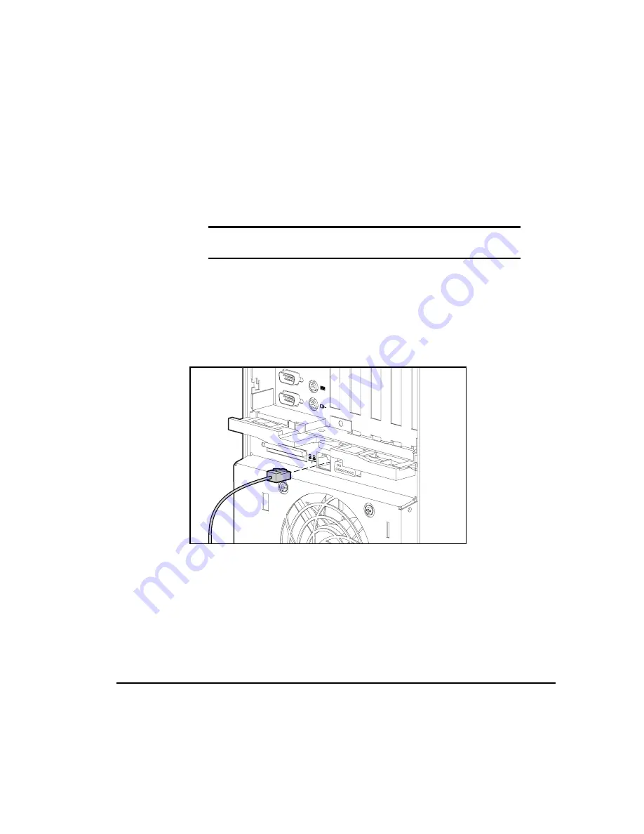
Insert one end of the network cable into the main network connection and
the other end into the RJ-45 connector on your workstation as shown in
the following figure. Make sure both connectors are securely joined.

TULAN028.EPS

Figure 5-2.


Attaching the network cable to the RJ-45 connector

Содержание Compaq 6000

Страница 1: ...the controller follow these steps 1 With Microsoft Windows NT Workstation 4 0 installed and running log in with administrator privileges 2 Insert the SmartStart for Workstations CD 3 Click Start Run 4 Type X NTSSD SETUP EXE where X is your CD ROM drive designation then click OK 5 Click Express then click Update 6 When the support software has been installed click Exit 7 When prompted restart your ...

Страница 2: ...the controller follow these steps 1 With Microsoft Windows NT Workstation 4 0 installed and running log in with administrator privileges 2 Insert the SmartStart for Workstations CD 3 Click Start Run 4 Type X NTSSD SETUP EXE where X is your CD ROM drive designation then click OK 5 Click Express then click Update 6 When the support software has been installed click Exit 7 When prompted restart your ...

Страница 3: ...Compaq Professional Workstation 6000 and 8000 Reference Guide Second Edition January 1998 Part Number 270217 002 Compaq Computer Corporation ...

Страница 4: ...rm without prior written consent from Compaq Computer Corporation 1998 Compaq Computer Corporation All rights reserved Printed in the U S A The software described in this guide is furnished under a license agreement or nondisclosure agreement The software may be used or copied only in accordance with the terms of the agreement Compaq Compaq Insight Manager ROMPaq QVision SmartStart NetFlex QuickFi...

Страница 5: ...ct Safety Information x Symbols on Equipment x Laser Precautions xi Rack Stability xi Getting Help xii Compaq Website xii Telephone Numbers xiii Chapter 1 Product Features Standard Features 1 2 Processors and System Memory 1 2 Expansion Slots 1 3 Drive Controller 1 3 Network Controller 1 3 Mass Storage 1 3 Standard Interfaces 1 4 Graphics Controllers 1 4 Audio 1 5 ROM 1 5 Power Supply 1 5 Compaq S...

Страница 6: ...ling Additional Mass Storage Devices 2 19 Installing a Processor 2 23 Upgrading the Processor 2 24 Chapter 3 Security Features Password Security 3 2 Establishing a Power On Password Using Computer Setup 3 3 Entering a Power On Password 3 4 Changing a Power On Password 3 4 Deleting a Power On Password 3 5 Clearing a Power On Password 3 7 Advanced Security Management 3 8 Establishing a Setup Passwor...

Страница 7: ...ation INSPECT 4 5 Create a Diagnostics Diskette 4 6 Manage a Diagnostics Partition 4 7 Exit from This Utility 4 7 ROM BIOS 4 7 Power On Self Test 4 7 Runtime Services 4 8 Upgrading the ROM BIOS 4 8 Chapter 5 Network Communications Identifying the Ethernet Connectors 5 2 Connecting to an Ethernet Cable 5 3 Installing the Network Drivers 5 4 Chapter 6 CD ROM Drive and PremierSound Audio System Using...

Страница 8: ...Synergy Graphics Controller 7 7 Upgrading Memory 7 7 Installing an Additional Controller 7 7 Resolutions and Color Support 7 8 GLoria L 3D Graphics Controller 7 9 Upgrading Memory 7 9 Installing an Additional Controller 7 9 Resolutions and Color Support 7 10 FireGL 4000 Graphics Controller 7 11 Resolution and Color Support 7 11 Chapter 8 Troubleshooting Checklist for Minor Problems 8 1 Troubleshoo...

Страница 9: ...ited States Only A 2 Modifications A 3 Cables A 3 Canadian Notice Avis Canadien A 3 Class B Equipment A 3 European Union Notice A 3 Japanese Notice A 4 Laser Devices A 4 Laser Safety Warnings A 5 Compliance with CDRH Regulations A 5 Compliance with International Regulations A 5 Laser Product Label A 5 Laser Information A 6 Battery Replacement Notice A 6 Mouse Compliance Statement A 6 Appendix B El...

Страница 10: ...sional Workstation 6000 and 8000 Reference Guide Comments 270217 002 File Name A FRNT DOC Last Saved On 12 17 97 10 51 AM COMPAQ CONFIDENTIAL NEED TO KNOW REQUIRED Appendix E Error Messages Appendix F External Connectors Pin Assignments F 1 Index ...

Страница 11: ...cument uses the following conventions to distinguish elements of text Keys Keys appear in boldface A plus sign between two keys indicates that they should be pressed simultaneously USER INPUT User input appears in a different typeface and in uppercase FILENAMES File names appear in uppercase italics Menu Options Command Names Dialog Box Names These appear in initial capital letters COMMANDS DIRECT...

Страница 12: ...Presents clarifying information or specific instructions NOTE Presents commentary sidelights or interesting points of information Product Safety Information Symbols on Equipment These icons may be located on equipment in areas where hazardous conditions may exist Any surface or area of the equipment marked with these symbols indicates the presence of electrical shock hazards Enclosed area contains...

Страница 13: ... of power WARNING To reduce the risk of injury from electrical shock remove all power cords to completely disconnect power from the system Laser Precautions WARNING To reduce the risk of injury from laser radiation or damage to the equipment observe the following precautions Allow only Compaq Authorized Service Technicians to repair the equipment Do not open any panels operate controls make adjust...

Страница 14: ... makes the rack bottom heavy and helps prevent the rack from becoming unstable See Configuration Rules in the Rack Planning and Installation Guide for the rules that govern the vertical placement of rack mounted components This information is also included in the Rack Builder diskette WARNING To reduce the risk of personal injury always ensure that the rack is adequately stabilized before extendin...

Страница 15: ...00 386 2172 Elsewhere call one of the numbers listed in the following table Compaq Worldwide Technical Support Telephone Numbers Location Voice FAX APD Asia Pacific Division 65 7503030 65 7504909 Argentina 54 1 313 3100 54 1 313 3100 Ext 21 Australia 61 2 9911 1955 61 2 9911 1900 Austria 0222 87816 16 0222 87816 82 Bahrain 973 210 214 Belgium 02 716 96 96 02 725 22 13 Brazil 55 11 5505 3600 55 11 ...

Страница 16: ...201 8776 36 1 201 9696 India 91 80 559 6023 Italy 392 57 90300 392 575 00686 Japan 0120 101589 81 3 5402 5959 Korea 82 2 523 3575 82 2 3471 0321 Malaysia 603 718 1636 Mexico 525 229 7910 525 229 7988 Netherlands 06 91681616 06 8991116 New Zealand 649 307 3969 Norway 22 072 020 22 072 021 Poland 48 2 630 3535 48 2 630 3553 Portugal 351 1 4120132 351 1 4120654 Singapore 65 7503030 65 7504909 South A...

Страница 17: ...maximize the latest microprocessor technology to meet customer application requirements Both are extremely powerful computers designed for complex applications such as 2D or 3D computer aided design CAD computer aided engineering CAE graphics applications animation and computer simulations Both deliver Error Checking and Correcting Memory PCI architecture integrated Fast Ethernet and an integrated...

Страница 18: ...encoding scheme for memory error detection and correction Specifically this feature detects and corrects all single bit memory errors and detects and reports double bit errors 32 64 or 128 MB EDO buffered 128 bit system memory expandable to 512 MB Supports 60 ns or faster EDO non parity 16 32 64 128 or 256 MB 4 K refreshed DIMMs added in pairs Compaq Professional Workstation 8000 Standard with two...

Страница 19: ...SI 3 Controller on PCI local bus Controller provides high performance options for up to seven SCSI devices in addition to the controller without using an expansion slot for an additional controller This controller uses a 16 bit data path and performs at a maximum data transfer rate of 40 megabytes per second MB s Optional controller boards are available for expanding storage capacity beyond seven ...

Страница 20: ... SCSI 3 Serial 2 Graphics Audio external volume control headphone two microphone connectors line in line out Parallel USB 2 hardware ready Keyboard Mouse 2 or 3 button Ethernet 10BaseT or 100TX RJ 45 and AUI connectors Graphics Controllers Depending on the model your workstation offers one of the following graphics controllers MGA Millennium II supports high performance 2D graphics GLoria Synergy ...

Страница 21: ...ED Audio The Compaq PremierSound Audio System features Integrated ported speaker built into the cabinet Integrated audio chip provides stereo sound and FM music synthesis Stereo inputs for CD ROM Monaural input for microphone 2 jacks Line in line out Headphone jack ROM Software upgradable firmware ROMPaq Utility used to upgrade ROM Power Supply The Compaq Professional Workstation 6000 and 8000 are...

Страница 22: ... configure the workstation and to load the system software thereby achieving a well integrated workstation that ensures maximum dependability and supportability For information concerning SmartStart refer to the Software Installation Guide included in the SmartStart for Workstations CD binder Security Features Security features are as follows Keyboard Password Administrator Password QuickLock Disk...

Страница 23: ...nts 270217 002 File Name B CH01 DOC Last Saved On 11 3 97 5 38 PM COMPAQ CONFIDENTIAL NEED TO KNOW REQUIRED Diagnostic Tools The software and firmware diagnostic tools available for your use are Power On Self Test POST Diagnostics DIAGS Computer Setup and Inspect ROMPaq utilities to upgrade flash ROMs For information on using the diagnostic tools see Chapter 4 ...

Страница 24: ...on the front panel of the workstation See the corresponding table for component names tulan022 eps 13 1 2 3 4 12 11 10 9 8 7 5 6 Figure 1 2 Identifying front panel components Table 1 1 Front Panel Components Ref Component Function 1 Volume down button Decreases sound level 2 Volume up button Increases sound level 3 Headphone jack Connect to headphone set 4 Microphone jack Connect to microphone 5 D...

Страница 25: ... compact disk from CD ROM drive 7 CD ROM drive LED Lights when the CD ROM drive is reading data 8 Diskette drive LED When lighted indicates the drive is reading or writing data 9 Front Bezel lock Locks the Front Bezel to the chassis 10 Power switch Turns the workstation on or off 11 Network activity LED When lighted indicates the workstation is receiving or sending data on the network 12 Hard driv...

Страница 26: ...to help identify its function See the corresponding table for component names TULAN018 EPS 8 7 6 5 10 11 12 4 3 1 2 9 13 Figure 1 3 Identifying rear panel components Table 1 2 Rear Panel Components Ref Component Function 1 Audio line in connector Connects a device that supplies sound such as a tape deck or CD player 2 Parallel port connector Connects a parallel device such as a printer 3 Microphon...

Страница 27: ...nects a serial device such as a serial printer 7 Serial port connector COM1 Connects a serial device such as a serial printer 8 Wide Ultra SCSI 3 connector Connects to external SCSI devices 9 Ethernet RJ 45 connector Connects to the Ethernet network 10 Mouse connector Connects to a mouse green icon 11 Keyboard connector Connects to a keyboard orange icon 12 Graphics port Connects to a monitor 13 E...

Страница 28: ...nts necessary to upgrade the workstation Installation guidelines and overviews for the following optional hardware are also included Expansion board Optional drives Additional memory Additional processor Refer to the documentation provided in the hardware upgrade kit for complete installation procedures For additional information refer to the Quick Setup poster included in the shipping box and the...

Страница 29: ...to the workstation is turned off and that the AC power cord is disconnected WARNING To reduce the risk of electrical shock fire or damage to the equipment do not plug telecommunications telephone connectors into the network interface controller NIC receptacles WARNING To reduce the risk of personal injury from hot surfaces allow the internal system components to cool before touching CAUTION Make s...

Страница 30: ...When unplugging from the electrical outlet grasp the cord by the plug 1 If the workstation is already on turn it off and disconnect the power cord from the wall outlet 2 Open the workstation by removing the outside panels and front bezel See the sections Removing the Small Access Panel Removing the Large Access Panel and Removing the Front Bezel in this chapter for instructions 3 Install any optio...

Страница 31: ...n If configuration settings are incorrect one or more devices may not work properly and you may receive an error message If this occurs run the Computer Setup utility again See Chapter 4 for instructions Installing Hardware Upgrades The Compaq Professional Workstation 6000 and 8000 chassis facilitates the installation of hardware upgrades Most hardware options are installed on the system board on ...

Страница 32: ...0 and 8000 Reference Guide Comments 270217 002 File Name C CH02 DOC Last Saved On 11 3 97 5 34 PM COMPAQ CONFIDENTIAL NEED TO KNOW REQUIRED Opening the Front Bezel To open the front bezel 1 If the keylock is locked unlock it by turning the key clockwise 2 Open the front bezel door tulan002 EPS Figure 2 1 Opening the front bezel ...

Страница 33: ... Disconnect any other external equipment 3 Open the front bezel 4 Loosen the thumbscrew above the speaker 5 Slide the small access panel toward the rear of the unit about 0 5 inch 1 5 cm and then slide the panel to the side of the workstation 6 Lift and remove the panel CAUTION Do not operate the workstation with the small access panel removed The small access panel is an integral part of the cool...

Страница 34: ...rkstation is on turn it off and disconnect the power cord 2 Disconnect any other external equipment 3 Open the front bezel 4 Loosen the two thumbscrews located on the left side of the front chassis see previous illustration 5 Slide the large access panel toward the rear of the unit 0 5 inch 1 5 cm 6 Lift and remove the panel CAUTION Do not operate the workstation with the large access panel remove...

Страница 35: ...ved On 11 3 97 5 34 PM COMPAQ CONFIDENTIAL NEED TO KNOW REQUIRED Removing Security Screws The Compaq Professional Workstation 6000 and 8000 ship with two security screws installed The screws secure the processor cage and expansion cage to the chassis To remove the security screws use a T 15 Torx screwdriver tulan007 EPS Figure 2 3 Removing the security screws ...

Страница 36: ...ocessor s Processor board s Terminator board if a single processor system Memory expansion board DIMM modules Switches and connectors To remove the processor cage 1 If the workstation is on turn it off and disconnect the power cord NOTE If you inadvertently remove the processor cage without turning OFF the power switch the workstation will automatically power down This is not however a recommended...

Страница 37: ...ly from the chassis 6 Remove the processor cage 1 2 3 tulan004 eps Figure 2 4 Removing the processor cage 7 Turn the cage over loosen the thumbscrew and lift the cover to gain access to the processor cage system board processor s processor board s terminator board if present DIMM modules memory expansion board switches and connectors 8 For information on upgrading or installing processor cage comp...

Страница 38: ... the processor cage be certain the plastic rails on the sides of the cage and the plastic rails on the chassis are properly aligned on both sides Visually locate the rails inside the chassis and guide the cage carefully into the chassis Otherwise the cage may jam part way into the chassis and the rails may be damaged IMPORTANT The processor cage must be properly installed in order for the workstat...

Страница 39: ...nd contains six expansion slots Four shared PCI ISA expansion slots slots 1 4 Two dedicated PCI local bus expansion slot slots 5 and 6 NOTE Although there are two physical connectors one ISA and one PCI for each shared PCI ISA slot the connectors are placed so that only one of the connector slots can have a board installed at a time The following figure shows a rear view of the workstation Expansi...

Страница 40: ...tion included with the option kit Additional information is also provided on the Quick Setup poster included in the shipping box and the expansion board installation hood label located on the inside of the large access panel 1 If the workstation is on turn it off and disconnect the power cord 2 Disconnect any other external equipment 3 Unlock and open the front bezel 4 Remove the small access pane...

Страница 41: ... CH02 DOC Last Saved On 11 3 97 5 34 PM COMPAQ CONFIDENTIAL NEED TO KNOW REQUIRED 7 Insert the expansion board TULAN011 eps Figure 2 8 Inserting an expansion board 8 Close the expansion slot latch to secure the board TULAN012 eps Figure 2 9 Securing an expansion board 9 Reassemble the workstation 10 Run the Computer Setup utility if necessary ...

Страница 42: ...en installing additional memory Use only 16 MB 32 MB 64 MB 128 MB or 256 MB buffered EDO DIMMs 3 3 volts DIMMs must be installed in matched pairs identical in size and speed The pairs of DIMMs however need not be of the same size For example two 16 MB DIMMs may be installed in slots 1 and 2 on the system board and two 32 MB DIMMs in slots 3 and 4 on the system board To optimize system performance ...

Страница 43: ...ED TO KNOW REQUIRED J1 J2 J3 J4 tulan036 EPS 4 3 2 1 Figure 2 10 Identifying DIMM slots on the processor cage system board tulan037 EPS 5 6 7 8 9 10 11 12 Figure 2 11 Identifying DIMM slots on the memory expansion board CAUTION Compaq recommends using Compaq DIMMs because they have been tested to ensure maximum performance and data intergrity Power On Self Test POST may not recognize non supported...

Страница 44: ... Prior to installing a DIMM read the important guidelines in the previous section To install a DIMM 1 If the workstation is on turn it off and disconnect the power cord 2 Disconnect any other external equipment 3 Unlock and open the front bezel 4 Remove the following components large access panel security screw processor cage 5 Place the processor cage on a flat surface and open the cage 6 If addi...

Страница 45: ...the socket IMPORTANT A memory module can only be installed in one way Match the notch on the module with the tab on the memory socket Push the module down into the socket ensuring that the module is fully inserted and properly seated 10 Close the DIMM socket latches tulan013 EPS s l o t 1 s l o t 2 s l o t 3 s l o t 4 2 2 1 Figure 2 12 Installing DIMMs on the processor cage system board 11 Reinsta...

Страница 46: ... bays for installing additional internal mass storage devices SCSI devices such as tape drives or hard drives can be installed in the two vacant removable media drive bays bays 6 and 7 All models have a drive cage that will accept a maximum of four 1 6 inch hard drives bays 0 3 or six 1 inch hard drives bays 0 5 tulan014 EPS 0 0 1 2 4 1 2 4 3 3 5 5 6 6 7 7 Figure 2 13 Identifying the drive bays wi...

Страница 47: ...D ROM drive IDE the bottom two half height 5 25 inch bays are vacant Two half height removable storage devices such as tape drives or hard drives can be installed in the bottom two removable media drive bays Also one full height storage device such as a DLT tape drive can be installed in the area occupied by the bottom two removable media drive bays To install a device in this area and to cable th...

Страница 48: ...0 and 8000 Reference Guide Writer Jean Schuck Project Compaq Professional Workstation 6000 and 8000 Reference Guide Comments 270217 002 File Name C CH02 DOC Last Saved On 11 3 97 5 34 PM COMPAQ CONFIDENTIAL NEED TO KNOW REQUIRED tulan016 EPS ...

Страница 49: ...stalling a drive Installing Hard Drives in the Drive Cage This section provides an overview for installing an additional hard drive For complete installation procedures refer to the documentation provided with the drive To install a hard drive in the drive cage 1 If the workstation is on turn off the power switch 2 Disconnect the power cord 3 Unlock and open the front bezel 4 Loosen the thumbscrew...

Страница 50: ...drive into the drive cage 8 Connect the signal and power cables Installing a Processor This section provides an overview for installing an additional Pentium Pro or Pentium II processor For complete installation procedures refer to the documentation provided with the processor upgrade kit Additional information is also available on the Quick Setup Poster and the hood labels To install an additiona...

Страница 51: ...ttached Refer to the documentation included with the processor upgrade kit for more complete instructions 7 To install an additional third Pentium Pro processor on a Compaq Professional Workstation 8000 Remove the terminator board Install the additional processor and a Processor Power Module on a new processor board Refer to the documentation included with the processor upgrade kit for more comple...

Страница 52: ...se switches refer to the Quick Setup poster or to the hood labels located on the interior of the large access panel and the small access panel For information about protecting the software on your workstation see Chapter 4 Table 3 1 Security Features Feature Purpose How It Is Established Setup Password Prevents reconfiguration of the workstation use of the Computer Setup utility until the Setup Pa...

Страница 53: ... through the integrated parallel interface Computer Setup from the Compaq Utilities menu Removable Media Control Prevents writing to the removable media drives Allows read only Computer Setup from the Compaq Utilities menu Front Bezel Lock Prevents access to the removable media area and the drive cage Keylock on front bezel Password Security Your workstation supports security password features whi...

Страница 54: ...approximately two seconds If you do not press F10 during this time you must turn the workstation off then on again to access the utility 3 Press Enter to bypass the welcome screens and display the main menu 4 From the main menu select Computer Setup and press Enter The workstation prompts you to reboot Press Enter and the workstation will restart into Computer Setup 5 From the Computer Setup main ...

Страница 55: ...three unsuccessful tries you must turn off the workstation then turn it on again before you can continue Changing a Power On Password To change the password 1 Turn on the workstation 2 When the key icon appears type your current password a slash or alternate delimiter character your new password another slash or alternate delimiter character and your new password again as shown current password ne...

Страница 56: ...L NEED TO KNOW REQUIRED Deleting a Power On Password To delete the password 1 Turn on the workstation 2 When the key icon appears type your current password followed by a slash or alternate delimiter character as shown current password NOTE Refer to the National Keyboard Delimiter Characters section in this chapter for information about alternate delimiter characters Completing this procedure dele...

Страница 57: ...nging or deleting your password depend on the keyboard that came with your workstation To determine the delimiter key required for changing or deleting your password find your keyboard in the following table Table 3 2 National Keyboard Delimiter Characters Arabic Greek Slovakian Belgian Hungarian Spanish BHCSY Italian Swedish Finnish Brazilian Japanese Swiss Chinese Hangul Taiwanese Czech Latin Am...

Страница 58: ...ards if necessary to locate the SW1 switch on the expansion cage system board The following figure shows the default switch setting for each switch on SW1 tulan038 EPS 1 2 3 4 Figure 3 1 Locating the SW1 switch and identifying default settings 5 On SW1 move switch 2 to the ON position not shown IMPORTANT Switch 2 has a default setting of OFF When the switch is OFF your system is password protected...

Страница 59: ...t Disable parallel port QuickLock QuickBlank Disable enable keyboard and mouse interface NOTE QuickLock QuickBlank must be used in combination with the Power On Password Establishing a Setup Password Establishing a Setup Password through the Computer Setup utility prevents reconfiguration of the workstation until the Setup Password is entered If your workstation does not have a Setup Password enab...

Страница 60: ... Setup and press Enter The workstation prompts you to reboot Press Enter and the workstation reboots into Computer Setup 5 From the Computer Setup main menu select the Security Management feature under Built In Devices 6 Locate the Setup Password option and follow the instructions on the screen to enable it 7 Save the configuration and exit the Computer Setup utility Entering the Setup Password To...

Страница 61: ...sword another slash or alternate delimiter character and your new password again as shown current password new password new password NOTE Refer to the National Keyboard Delimiter Characters section in this chapter for information about the alternate delimiter characters NOTE Type carefully for security reasons the characters you type do not appear on the screen Completing this procedure causes the...

Страница 62: ...ut alternate delimiter characters Completing this procedure deletes the password until you establish a new one through Security Management NOTE The Setup Password may also be deleted by using the Computer Setup utility Follow the Establishing a Setup Password procedure Locate the Setup Password option and follow the instructions to delete the Setup Password The Setup utility will provide an option...

Страница 63: ...default settings 5 On SW1 move switch 2 to the ON position not shown IMPORTANT Switch 2 has a default setting of OFF When the switch is OFF your system is password protected To re enable password protection you MUST return the switch to its default position later in this procedure 6 Restart the workstation to erase your password from system memory NOTE Clearing the Setup Password will also clear t...

Страница 64: ... corner of the screen for approximately two seconds If you do not press F10 during this time you must turn the workstation off then on again to access the utility 3 Press Enter to bypass the welcome screens and display the main menu 4 From the main menu select Computer Setup and press Enter The workstation prompts you to reboot Press Enter and the workstation will restart into Computer Setup 5 Fro...

Страница 65: ...uring this time you must turn the workstation off then on again to access the utility 3 Press Enter to bypass the welcome screens and display the main menu 4 From the main menu select Computer Setup and press Enter The workstation prompts you to reboot Press Enter and the workstation will restart into Computer Setup 5 From the Computer Setup main menu select Communications under Built In Devices D...

Страница 66: ...ion you must enter the Power On Password that you established in Security Management Therefore you must establish a Power On Password in order to utilize Quick Lock and Quick Blank Enabling QuickLock and QuickBlank To enable the QuickLock and QuickBlank features the Power On Password must be enabled Then 1 Turn on the workstation 2 When the cursor appears in the upper right corner of the screen pr...

Страница 67: ... when entering Energy Saver Mode the Power Management option must be enabled For more information about the various screen and configuration options see Chapter 4 7 Check the function desired by clicking in the appropriate box 8 Save the configuration and exit the utility Disabling the Keyboard and Mouse Interface Once in an application enter the QuickLock key combination Ctrl Alt L The keyboard a...

Страница 68: ...r On Password NOTE For security reasons the characters you type do not appear on the screen The application will not be affected by the characters typed CAUTION If your workstation does not have a Setup Password enabled then the ROM is not write protected Updates may occur that could disrupt the operating system The Setup Password is disabled when the workstation leaves the factory Front Bezel Loc...

Страница 69: ...e help If you have reformatted your hard drive and removed the Compaq Utilities partition it can be reinstalled by using the Compaq SmartStart for Workstations CD or you can download Setup and User Diagnostics diskettes from the Compaq website at http www compaq com NOTE For more information about installing your operating system drivers and other support software refer to the Workstation Referenc...

Страница 70: ...configuration parameters when resolving problems To get an overview of the workstation s hardware To modify settings for graphics processor memory audio storage communications and input devices To enable or disable removable media drive boot ability To enable or disable removable media drive write control To enable or disable the serial or parallel ports To resolve errors when a system configurati...

Страница 71: ... set or change your Power On Password To set or change the Setup administrator Password which protects the workstation configuration To password protect access to your system To set or change QuickLock QuickBlank features See Chapter 3 to identify the security features their purposes and how to establish them Power Management Use the Power Management feature of Computer Setup in the following inst...

Страница 72: ...zed dealer reseller or service provider in analyzing the system by allowing the service provider to reproduce the same environment on another workstation for testing To run Computer Checkup TEST 1 Turn on only the external devices that you wish to test You may wish to leave the printer connected to log error messages 2 Access the Compaq Utilities menu 3 From the Compaq Utilities menu select Comput...

Страница 73: ... or unattended testing decide to stop on errors or choose to print or file a log of errors 7 Follow the instructions on the screen as the diagnostic tests are run on the devices When the testing is complete the screen displays the test option menu again NOTE When running TEST record any error message numbers and have them available when you contact your Compaq authorized dealer reseller or service...

Страница 74: ...oth Setup or Diagnostics diskettes from the diagnostics partition To create the diskettes 1 Turn on or restart the workstation If Windows NT is running click Start Shut Down Restart the computer Immediately after the workstation completes Power On Self Test POST which is indicated on the screen by the memory check the system beeps twice and the cursor moves to the upper right corner of the screen ...

Страница 75: ...ement hard drive If the diagnostics software is deleted you will no longer be able to access the Compaq Utilities menu Exit from This Utility Use this option to exit the Compaq Utilities menu ROM BIOS Your workstation contains a set of software called Basic Input Output System BIOS stored in Read Only Memory ROM on the system board The BIOS contains a set of routines for Power On Self Test POST an...

Страница 76: ...m the BIOS still provides some runtime services to the operating system For instance the BIOS provides information to the operating system on how many processors are installed how the system interrupts are configured and information on the disk drives BIOS also provides information about your workstation s configuration and maintenance Upgrading the ROM BIOS The ROM BIOS on your workstation may be...

Страница 77: ...ter exchange information from device to device and run common software programs Your workstation comes Ethernet network ready which means that it has an integrated network controller and network device drivers on the Compaq SmartStart for Workstations CD The integrated Netelligent network controller is a PCI bus mastering dual speed 10Base T standard 100Base TX controller that will automatically d...

Страница 78: ...ifying the Ethernet Connectors The following Ethernet connectors are located on the rear panel of the workstation RJ 45 8 pin connector AUI thick coax cable 10Base T only 15 pin connector 1 2 TULAN027 EPS Figure 5 1 Identifying the Ethernet connectors WARNING To reduce the risk of electrical shock fire or damage to the equipment do not plug telecommunications telephone connectors into the network ...

Страница 79: ...tation Each type requires different equipment and installation procedures as explained in the following sections IMPORTANT To avoid configuration problems do not attempt to utilize the RJ 45 and AUI connectors simultaneously Attaching a Network Cable to the RJ 45 Connector Insert one end of the network cable into the main network connection and the other end into the RJ 45 connector on your workst...

Страница 80: ...I connector on your workstation Make sure both connectors are securely joined TULAN029 EPS Figure 5 3 Attaching the network cable to an AUI connector Installing the Network Drivers The device drivers in the network software enable the workstation to communicate with the network For information about installing drivers operating systems and other support software refer to the Workstation Reference ...

Страница 81: ...ndom access read only storage device capable of retrieving data from a removable compact disc Using the Slot Load CD ROM Drive 1 Turn on the workstation if it is not already on 2 Hold the compact disc by the edges label side up being careful not to touch the flat surfaces of the disc and insert it straight into the slot Discs inserted at an angle may not be accepted The drive performs a diagnostic...

Страница 82: ...c 3 When the busy indicator turns green the drive is ready to receive commands and data may be retrieved from the disc 4 To remove the compact disc press the Eject button IMPORTANT Certain applications or operating system software may disable the load unload button to prevent accidental damage to the disc If the load unload button is disabled by the application software it will not operate CAUTION...

Страница 83: ...more efficiently and quickly in the future NOTE Some software compact discs take control of the hardware volume controls If this occurs adjust the volume controls before starting the software Read the software manufacturer s instructions that accompany the compact disc before you attempt to use it Information to look for includes How much hard disk space will this program require Do you have enoug...

Страница 84: ...d sounds as data on the hard drive This sound data may be used in many ways for example you can enhance presentation data with voice and music If you choose to upgrade your audio system you must disable the integrated audio controller IMPORTANT Do not remove the ESS 1868 driver from the Drivers window in the Control Panel Follow the instructions below 1 From the Control Panel in Windows NT select ...

Страница 85: ...e that the CD ROM drive operates properly observe the following precautions Do not move the drive during operation This may cause it to malfunction during reading Avoid exposing the drive to sudden changes in temperature as condensation may form inside the unit If the temperature suddenly changes while the drive is on wait at least one hour before you turn off the power If you operate the unit imm...

Страница 86: ...on 6000 and 8000 Reference Guide Comments 270217 002 File Name G CH06 DOC Last Saved On 11 3 97 2 07 PM COMPAQ CONFIDENTIAL NEED TO KNOW REQUIRED Safety Precautions If any object or liquid falls into the slot immediately unplug the workstation and have it checked by an authorized Compaq service provider ...

Страница 87: ...ity of the picture you see depends on the resolution of your monitor and the number of colors that the graphics controller can display High resolution graphics with many colors requires that the graphics controller have its own memory The Compaq Professional Workstation 6000 and 8000 come standard with one of the following graphics controllers MGA Millennium II GLoria Synergy GLoria L 3D FireGL 40...

Страница 88: ... 7 1 Graphics Controllers Configurations for Multi Monitor Support Graphics Controller Hardware Configurations MGA Millennium II Supports one monitor For multiple monitor support install additional controllers GLoria Synergy Supports one monitor For multiple monitor support install additional controllers GLoria L 3D Supports one monitor For multiple monitor support install additional controllers N...

Страница 89: ...g additional controllers Single buffer and double buffer 16 Bit and 32 Bit Z Buffer resolution modes Upgrading Memory To install a memory upgrade module on the MGA Millennium II graphics controller refer to the documentation included in the memory upgrade kit Installing an Additional Controller The MGA Millennium II graphics controller installed on your workstation provides single monitor support ...

Страница 90: ...t Table 7 2 Maximum Color Support MGA Millennium II Double Buffer Mode 16 Bit Z Buffer Resolutions 4 MB 8 MB 16 MB 1800 x 1440 65 536 1920 x 1200 65 536 1920 x 1080 256 65 536 1920 x 1034 I 256 65 536 1600 x 1200 256 65 536 1600 x 1024 256 16 777 216 1280 x 1024 65 536 16 777 216 1152 x 864 256 65 536 16 777 216 1024 x 768 256 16 777 216 16 777 216 800 x 600 65 536 16 777 216 16 777 216 640 x 480 ...

Страница 91: ...NTIAL NEED TO KNOW REQUIRED Table 7 3 Maximum Color Support MGA Millennium II Double Buffer Mode 32 Bit Z Buffer Resolutions 4 MB 8 MB 16 MB 1800 x 1440 256 1920 x 1200 256 1920 x 1080 65 536 1920 x 1034 I 65 536 1600 x 1200 65 536 1600 x 1024 65 536 1280 x 1024 256 16 777 216 1152 x 864 65 536 16 777 216 1024 x 768 65 536 16 777 216 800 x 600 65 536 16 777 216 16 777 216 640 x 480 16 777 216 16 7...

Страница 92: ...olutions 4 MB 8 MB 16 MB 1800 x 1440 256 65 536 65 536 1920 x 1200 256 16 777 216 16 777 216 1920 x 1080 65 536 16 777 216 16 777 216 1920 x 1034 I 65 536 16 777 216 16 777 216 1600 x 1200 65 536 16 777 216 16 777 216 1600 x 1024 65 536 16 777 216 16 777 216 1280 x 1024 16 777 216 16 777 216 16 777 216 1152 x 864 16 777 216 16 777 216 16 777 216 1024 x 768 16 777 216 16 777 216 16 777 216 800 x 60...

Страница 93: ...pport by installing additional controllers Single buffer and double buffer 16 bit Z buffer resolution modes Upgrading Memory To install a memory upgrade module on the GLoria Synergy graphics controller refer to the documentation included in the memory upgrade kit Installing an Additional Controller The GLoria Synergy graphics controller installed on your workstation provides single monitor support...

Страница 94: ...REQUIRED Resolutions and Color Support Table 7 5 Maximum Color Support GLoria Synergy Resolutions 4 MB 8 MB 1920 x 1200 256 32 768 1920 x 1080 256 32 768 1600 x 1280 32 768 32 768 1600 x 1200 32 768 32 768 1600 x 1000 32 768 16 777 216 1536 x 1152 32 768 32 768 1280 x 1024 32 768 16 777 216 1152 x 864 16 777 216 16 777 216 1024 x 768 16 777 216 16 777 216 800 x 600 16 777 216 16 777 216 640 x 480 ...

Страница 95: ...nitor support expandable to multiple monitor support by installing additional controllers Upgrading Memory To install a memory upgrade module on the GLoria L 3D graphics controller refer to the documentation included in the memory upgrade kit Installing an Additional Controller The GLoria L 3D graphics controller installed on your workstation provides single monitor support To upgrade your worksta...

Страница 96: ... Last Saved On 10 30 97 2 22 PM COMPAQ CONFIDENTIAL NEED TO KNOW REQUIRED Resolutions and Color Support Table 7 6 Maximum Color Support GLoria L 3D Single Buffer Mode Double Buffer Mode Resolution Colors Colors 1600 x 1200 16 777 216 32 768 1280 x 1024 16 777 216 32 768 1152 x 864 16 777 216 32 768 1024 x 768 16 777 216 32 768 800 x 600 16 777 216 32 768 ...

Страница 97: ...ntroller with 1 MB DRAM Connector and support for stereographics display Standard 15 MB 3D RAM frame buffer and Z buffer Standard 16 MB CDRAM texture buffer memory Resolution and Color Support Table 7 7 Maximum Color Support FireGL 4000 Graphics Controller Single Buffer Mode Resolution Color Refresh Rate Hz 1280 x 1024 16 7 M 85 1024 x 768 16 7 M 100 800 x 600 16 7 M 120 640 x 480 16 7 M 120 Stere...

Страница 98: ...ion monitor or software refer to the following list of general suggestions before taking further action Check that the workstation and monitor are plugged into a working electrical outlet Check to see that the workstation is turned on and the green power light is on Check to see that the monitor is turned on and the green monitor light is on Turn up the brightness and contrast controls of the moni...

Страница 99: ...ou to press the spacebar to invoke the last known good menu press the spacebar Windows NT remembers your last working configuration and runs it Troubleshooting Common Problems Although your workstation is configured for your particular hardware and software problems you encounter while working may not be unique Eliminating the typical problems described in this section may save you time and money ...

Страница 100: ...power source are unplugged Ensure that cables connecting the workstation and the external source are plugged in properly A defective PCI or ISA card has been installed Remove any adapter card that was just installed Boards or cages are not properly installed Enure boards are properly seated in the Processor Cage Ensure cages are properly installed in unit Workstation doesn t automatically display ...

Страница 101: ...ion does not beep during the power on self test POST Speaker cable is not properly attached Ensure that speaker cable is connected Speaker volume is turned down Press volume up button Win Windows NT select Volume Control under Accessories and adjust Headphones are plugged in Unplug headphones Workstation powered off automatically The unit temperature was exceeded The fan may be blocked 1 Unit is i...

Страница 102: ...y inserted Remove diskette and reinsert Drive button is not pushed in Push in drive button Software program is damaged Check the program diskettes or reinstall software from original media Drive cable is not properly connected Reconnect drive cable Diskette drive cannot write to a diskette Diskette is not formatted Format the diskette Diskette is write protected Use another diskette or remove the ...

Страница 103: ...urred with a disk transaction The directory structure is bad or there is a problem with a file Run CHKDSK to check for fragmentation Diskette drive cannot read a diskette Diskette is not formatted Format the diskette You are using the wrong diskette type for the drive type Check the type of drive you are using and use the correct diskette type Drive not found Cable is loose Check connections Nonsy...

Страница 104: ...connections are not correct Check the cable connection from the monitor to the workstation and to the electrical outlet The QuickBlank feature has been enabled through Computer Setup Run Computer Setup and disable the QuickBlank feature The energy saver feature has been enabled Press any key or type your password and wait a few moments for the screen to activate The RGB Red Green Blue input switch...

Страница 105: ...s are wrong This indicates that either the cabling or monitor impedance is incorrect 1 Ensure that the Red Green and Blue BNC cables are connected to the corresponding monitor connectors 2 Be sure your monitor s RGB inputs are set to 75 ohms Audio Problems Table 8 4 Audio Problems and Solutions Problem Possible Cause Possible Solution Sound does not come out of the speaker Software volume control ...

Страница 106: ...r drivers for your application are not installed Install the correct printer drivers for your application If you are on a network you may not have made the connection to the printer Make the proper network connections to the printer Printer will not turn on The cables may not be connected properly Reconnect all cables and check the power cord and electrical outlet Prints garbled information The co...

Страница 107: ...evice is not recognized as part of the system Computer Setup or the SCSI software utility has not been run to configure the new device Run Computer Setup or the SCSI software utility Cable s of new external device are loose or power cables are unplugged Ensure that all cables are properly and securely connected and that pins in the cable or connector are not bent down Power switch of new external ...

Страница 108: ...ng expansion board or reconfigure the network controller If the address is changed ensure that the drive parameters match the new I O address for the network controller Setup utility reports unprogrammed EEPROM Possible I O address conflict with another expansion board Either remove and reconfigure the conflicting expansion board or reconfigure the network controller If the address is changed ensu...

Страница 109: ...d ensure that the drive parameters match the new I O address for the network controller The cable is not securely connected Ensure that the cable is securely attached to the network connector and that the other end of the cable is securely attached to the correct device The cable is attached to the incorrect connector Ensure that the cable is attached to the correct connector There is a problem wi...

Страница 110: ...e interrupt of an expansion board Run the Setup utility and modify the network controller memory value Network controller stopped working when an expansion board was added to the workstation Network drivers are not loaded or driver parameters do not match current configuration Make sure the network drivers are loaded and that the driver parameters match the configuration of the network controller ...

Страница 111: ...her end of the cable is securely attached to the correct device The network controller is defective Contact your Compaq authorized service provider Memory Problems Table 8 8 Memory Problems and Solutions Problem Possible Cause Possible Solution Out of Memory error Memory configuration may not be set up correctly Run Computer Setup You have run out of memory to run the application Check the applica...

Страница 112: ...lem Possible Cause Possible Solution System will not boot from CD ROM drive The CD ROM boot is not enabled through the Setup utility Run the Setup utility and set the drive priorities Data read from CD ROM drive is inconsistent or drive cannot read data Paper or plastic label has been applied to surface of the CD in use Remove label and any adhesive residue CD ROM devices are not detected driver i...

Страница 113: ... installed in a residential environment i e personal computers The FCC requires devices in both classes to bear a label indicating the interference potential of the device as well as additional operating instructions for the user The rating label on the device shows which class A or B the equipment falls into Class B devices have an FCC logo or FCC ID on the label Class A devices do not have an FC...

Страница 114: ...dio or television reception which can be determined by turning the equipment off and on the user is encouraged to try to correct the interference by one or more of the following measures Reorient or relocate the receiving antenna Increase the separation between the equipment and receiver Connect the equipment into an outlet on a circuit different from that to which the receiver is connected Consul...

Страница 115: ...n order to maintain compliance with FCC Rules and Regulations Canadian Notice Avis Canadien Class B Equipment This Class B digital apparatus meets all requirements of the Canadian Interference Causing Equipment Regulations Cet appareil numérique de la classe B respecte toutes les exigences du Règlement sur le matériel brouilleur du Canada European Union Notice Products with the CE Marking comply w...

Страница 116: ...evices The CD ROM drive contains a laser device All Compaq systems equipped with a laser device comply with safety standards including International Electrotechnical Commission IEC 825 With specific regard to the laser the equipment complies with laser product performance standards set by government agencies as a Class 1 laser product The product does not emit hazardous light the beam is totally e...

Страница 117: ...ed Service Technicians to repair the laser equipment Compliance with CDRH Regulations The Center for Devices and Radiological Health CDRH of the U S Food and Drug Administration implemented regulations for laser products on August 2 1976 These regulations apply to laser products manufactured from August 1 1976 Compliance is mandatory for products marketed in the United States Compliance with Inter...

Страница 118: ...d risk of personal injury if the battery is incorrectly replaced or mistreated WARNING To reduce the risk of personal injury do not attempt to recharge the battery disassemble it immerse it in water or dispose of it in fire Batteries battery packs and accumulators should not be disposed of together with the general household waste In order to forward them to recycling or proper disposal please use...

Страница 119: ...lectrostatic sensitive parts in their containers until they arrive at static free workstations Place parts on a grounded surface before removing them from their containers Avoid touching pins leads or circuitry Always be properly grounded when touching a static sensitive component or assembly Grounding Methods There are several methods for grounding Use one or more of the following methods when ha...

Страница 120: ...e Name K APPB DOC Last Saved On 10 23 97 4 57 PM COMPAQ CONFIDENTIAL NEED TO KNOW REQUIRED If you do not have any of the suggested equipment for proper grounding have an Authorized Compaq Reseller install the part NOTE For more information on static electricity or assistance with product installation contact your Authorized Compaq Reseller ...

Страница 121: ...he country where you use the server For more information on power cord set requirements contact your Authorized Compaq Dealer General Requirements The requirements listed below are applicable to all countries The length of the power cord must be at least 6 0 feet 1 8 m and a maximum of 12 feet 3 7 m The power cord set must be approved by an acceptable accredited agency responsible for evaluation i...

Страница 122: ... Sweden SEMKO 1 Switzerland SEV 1 United Kingdom BSI 1 United States UL 2 Notes 1 Flexible cord must be HAR Type HO5VV F 3 conductor 1 0 mm2 conductor size Power cord set fittings appliance coupler and wall plug must bear the certification mark of the agency responsible for evaluation in the country where it will be used 2 Flexible cord must be Type SVT or equivalent No 18 AWG 3 conductor Wall plu...

Страница 123: ...ng Computer Setup Computer Setup automatically detects and configures most Compaq components including Compaq hard drives If your workstation has a Compaq hard drive go to the next section Preparing the Workstation for Battery Installation If your workstation has a third party hard drive you MUST complete the following steps before installing the battery 1 Run Computer Setup and record the drive t...

Страница 124: ...kstation for Battery Installation To prepare the workstation 1 If the workstation is on turn it off 2 Unplug the workstation 3 Unlock and open the front bezel 4 Remove the large access panel 5 If the expansion board cage security screw is in place remove it 6 Remove the expansion board cage 7 Locate the jumper on the expansion cage system board as shown in Figure D 1 8 Remove any expansion boards ...

Страница 125: ...tem board A second battery is installed when the first becomes inoperative WARNING The battery clock module contains a lithium battery that could explode if mishandled Do not abuse recharge disassemble or dispose of in fire or heat about 90 degrees C incinerate or expose to water or fire Use only battery clock modules supplied by Compaq Computer Corporation 1 Remove and discard the protective cove...

Страница 126: ...25 EPS Figure D 2 Changing the jumper from pins 6 7 to pins 5 6 5 Place the pale blue sticker included with the battery kit above the power connector on the back of the workstation 6 Replace the expansion board cage and workstation cover 7 Plug in the workstation 8 Turn on the workstation 9 Run Computer Setup to reconfigure the system 10 If the workstation has a Compaq hard drive you have now succ...

Страница 127: ...ondition Table E 1 POST Error Messages and Codes Error Code Probable Source of Problem Action 101 ROM Error System ROM checksum Contact your Compaq authorized service provider 101 Option ROM Checksum Error Options ROM checksum Contact your Compaq authorized service provider 102 System Board Failure DMA timers etc Replace the Expansion Cage System Board Run the Computer Setup utility 162 System Opt...

Страница 128: ...pe Mismatch RAM failure Contact your Compaq authorized service provider 203 Memory Address Error RAM failure Contact your Compaq authorized service provider 205 Memory Error Cache memory error Run the Computer Checkup or Diagnostics utility 207 ECC Corrected Single Bit Errors in DIMM SIMM Pair s A memory error on one of the installed DIMMs has been detected and corrected with the system s ECC logi...

Страница 129: ... a key stuck or something on the keyboard Ensure that the keyboard is plugged in Replace the keyboard if necessary 303 Keyboard Controller Error I O keyboard controller Contact your Compaq authorized service provider 304 Keyboard or System Unit Error Keyboard Contact your Compaq authorized service provider 40X Parallel Port X Address Assignment Conflict Both external and internal ports are assigne...

Страница 130: ... Floppy Port Address Assign ment Conflict Configuration error Run Computer Setup 612 Secondary Floppy Port Address Assignment Conflict Configuration error Run Computer Setup 1151 System Board COM Port 1 Address Assignment Conflict Configuration Error Run Computer Setup 1152 System Board COM Port 2 Address Assignment Conflict Configuration Error Run Computer Setup 1155 COM Port Address Assignment C...

Страница 131: ...ssignment Conflict IDE configuration Run Computer Setup 1772 Secondary Disk Port Address Assignment Conflict IDE configuration Run Computer Setup 1780 Disk 0 failure IDE hard drive failure Contact your Compaq authorized service provider 1781 Disk 1 Failure IDE hard drive failure Contact your Compaq authorized service provider 1782 Disk Controller Failure IDE circuitry failure Contact your Compaq a...

Страница 132: ...dary Controller or Disk Failure An error has been detected with the CD ROM interface Run the Diagnostics utility A Critical Error Occurred Prior to this Power Up Critical failure POST recorded into the wellness log None A Collectable Memory Error Occurred Prior to this Power Up Single bit ECC during POST None Audible beep Power on successful None Invalid Electronic Serial Number The electronic ser...

Страница 133: ...W REQUIRED Appendix F External Connectors Pin Assignments The following tables provide pin assignments for each external connector on the Compaq Professional Workstation 6000 and 8000 Table F 1 Keyboard Connector and Icon Orange Pin Signal 188368bd AI KEYBD EPS 1 2 4 6 3 5 1 2 3 4 5 6 Data Unused Ground 5 VDC Clock Unused Table F 2 Mouse Connector and Icon Green Pin Signal 188368bc AI MOUSE EPS 1 ...

Страница 134: ...D TO KNOW REQUIRED Table F 3 Parallel Interface Connector and Icon Pin Signal 188368bf AI PARALLEL EPS 1 2 3 4 5 6 7 8 9 10 11 12 13 14 15 16 17 18 19 20 21 22 23 24 25 1 2 3 4 5 6 7 8 9 10 11 12 13 14 15 16 17 18 25 Strobe Data Bit 0 Data Bit 1 Data Bit 2 Data Bit 3 Data Bit 4 Data Bit 5 Data Bit 6 Data Bit 7 Acknowledge Busy Paper End Select Auto Linefeed Error Initialize Printer Select IN Signa...

Страница 135: ...ents 270217 002 File Name O APPF DOC Last Saved On 11 3 97 4 19 PM COMPAQ CONFIDENTIAL NEED TO KNOW REQUIRED Table F 4 Serial Interfaces Connector and Icon Pin Signal 188368be AI SERIAL EPS 3 4 5 7 9 6 8 1 2 1 2 3 4 5 6 7 8 9 Carrier Detect Receive Data Transmit Data Data Terminal Ready Signal Ground Data Set Ready Request to Send Clear to Send Ring Indicator ...

Страница 136: ...L NEED TO KNOW REQUIRED Table F 5 Monitor Connector and Icon Pin Signal 188368bg AI VIDEO EPS 1 2 3 4 5 6 7 8 10 11 12 13 14 15 Key 1 2 3 4 5 6 7 8 9 10 11 12 13 14 15 Red Analog Green Analog Blue Analog Monitor ID Bit2 Ground Ground Analog Ground Analog Ground Analog Not Connected Ground Monitor ID Bit 0 Bi directional Data SDA Horizontal Sync Vertical Sync Data Clock SCL For DDC support I2C moni...

Страница 137: ...mments 270217 002 File Name O APPF DOC Last Saved On 11 3 97 4 19 PM COMPAQ CONFIDENTIAL NEED TO KNOW REQUIRED Table F 6 USB Connector Pin Signal 1 2 3 4 1 2 3 4 1 2 3 4 VCC Data Data Ground Table F 7 Ethernet RJ 45 Connector and Icon Pin Signal 1 3 5 7 2 4 6 8 1 2 3 4 5 6 7 8 Transmit Data Transmit Data Receive Data Unused Unused Receive Data Unused Unused ...

Страница 138: ...ED TO KNOW REQUIRED Table F 8 Ethernet AUI Connector Pin Signal 8 7 6 5 4 3 2 1 15 14 13 12 11 10 9 1 2 3 4 5 6 7 8 9 10 11 12 13 14 15 Signal Ground CI A Control In Circuit A DO A Data Out Circuit A Signal Ground DI A Data In Circuit A Signal Ground No Connect Signal Ground CI B Control In Circuit B DO B Data Out Circuit B Signal Ground DI B Data In Circuit B VP Voltage Plus 12V Signal Ground No ...

Страница 139: ...MPAQ CONFIDENTIAL NEED TO KNOW REQUIRED Table F 9 Wide Ultra SCSI Connector Connector and Icon SCSIWIDE EPS 1 34 35 68 Pin Signal Pin Signal 1 16 17 18 19 20 34 35 36 37 38 39 40 41 42 43 44 45 46 47 48 49 50 Ground TERMPWR Reserved Ground D12 D13 D14 D15 DP1 D0 D1 D2 D3 D4 D5 D6 D7 DP0 Ground 51 52 53 54 55 56 57 58 59 60 61 62 63 64 65 66 67 68 TERMPWR Reserved Ground ATN Ground BSY ACK RST MSG ...

Страница 140: ...17 002 File Name O APPF DOC Last Saved On 11 3 97 4 19 PM COMPAQ CONFIDENTIAL NEED TO KNOW REQUIRED Table F 10 Line In Audio Connector Connector and Icon 1 8 inch Miniphone Table F 11 Line Out Audio Connector Connector and Icon 1 8 inch Miniphone Table F 12 Microphone Connector Connector and Icon Blue Stereo 1 8 inch Miniphone ...

Страница 141: ...r Jean Schuck Project Compaq Professional Workstation 6000 and 8000 Reference Guide Comments 270217 002 File Name O APPF DOC Last Saved On 11 3 97 4 19 PM COMPAQ CONFIDENTIAL NEED TO KNOW REQUIRED Table F 13 Headphone Connector Connector and Icon Stereo 1 8 inch Miniphone ...

Страница 142: ...nstallation preparations D 2 recycling notice A 6 replacing D 1 running Computer Setup D 1 Bay configurations Removable Media Area 2 20 BIOS 4 7 runtime services 4 8 upgrading 4 8 Blank bezel removing 2 20 Blank screen troubleshooting 8 7 C CD ROM drive cleaning 6 5 inserting CD described 6 1 illustrated 6 1 operating precautions 6 5 troubleshooting 8 15 using CD ROM software 6 3 CDs playing audio...

Страница 143: ... Workstations features 1 6 Compaq Utilities accessing 4 1 options 4 2 Compaq website xii Components blank bezel removing 2 20 DIMMs installing described 2 17 illustrated 2 18 expansion boards installing described 2 13 illustrated 2 14 front panel described 1 8 illustrated 1 8 hard drive installing in drive cage 2 22 installing in Removable Media Area 2 20 installation precautions 2 2 installation ...

Страница 144: ...rd illustrated 2 16 processor cage system board illustrated 2 16 DIMM slot precaution for inserting DIMM 2 18 Disk controller See Wide Ultra SCSI 3 Controller Diskette Boot disabling 3 13 Diskette drive troubleshooting 8 5 Diskette Write disabling 3 13 Drive bay possible configurations described 2 19 illustrated 2 19 Removable Media Area overview 2 20 Drive Cage installing hard drive described 2 2...

Страница 145: ...e controller 1 3 expansion slots 1 3 external connectors 1 4 front panel components 1 8 graphics controllers 1 4 memory 1 2 network controller 1 3 power supply 1 5 PremierSound Audio System 1 5 processors 1 2 rear panel components 1 10 ROM 1 5 security 1 6 SmartStart for Workstations 1 6 FireGL 4000 graphics controller features 7 11 multiple monitor support 7 2 supported resolutions and colors 7 1...

Страница 146: ...ading memory 7 9 MGA Millennium II features 7 3 installing additional controller 7 3 multiple monitor support 7 2 supported resolutions and colors 7 4 upgrading memory 7 3 using multiple monitors 7 2 Grounding Methods B 1 H HAL multiprocessing 2 24 Hard drive configurations described 2 19 illustrated 2 19 important installation guidelines 2 21 installing 2 22 installing in Removable Media Area ill...

Страница 147: ...ck front bezel 2 5 3 17 L Large access panel removing described 2 7 illustrated 2 6 Limited Warranty 1 11 Lock front bezel 2 5 3 17 Logon Password 3 1 M Mass storage devices See also Hard drive installation overview 2 19 possible bay configurations described 2 19 Memory See also Graphics controller upgrading memory important installation guidelines 2 15 installation overview 2 15 installing descri...

Страница 148: ...tor pin assignment F 2 disabling 3 14 Parallel interface control described 3 2 Password Power On changing 3 4 clearing 3 7 deleting 3 5 entering 3 4 establishing 3 3 Setup changing 3 10 clearing 3 11 deleting 3 11 entering 3 9 establishing 3 8 PCI ISA shared expansion slot 2 12 Pentium II processor upgrading 2 24 Pentium Pro processor upgrading 2 24 Pin assignment Ethernet AUI connector F 6 Ethern...

Страница 149: ...essor installing 2 23 upgrading 2 24 Processor cage DIMM slot illustrated 2 16 removing described 2 9 illustrated 2 10 replacing illustrated 2 11 Processor cage rails aligning illustrated 2 11 precaution 2 11 Product Safety Information x Prompted Diagnostics 4 5 Q Quick Check Diagnostics 4 5 QuickBlank described 3 2 3 15 enabling 3 15 QuickLock described 3 2 3 15 enabling 3 15 R Rails attaching to...

Страница 150: ...r pin assignment F 3 disabling 3 14 Serial interface control described 3 2 Setup Password changing 3 10 clearing 3 11 deleting 3 11 described 3 1 entering 3 9 establishing 3 8 Small access panel illustrated 2 6 removing 2 6 SmartStart features 1 6 Software Compaq 4 1 Compaq SmartStart for Workstations 1 6 diagnostic tools listed 1 7 Software problems solving 8 2 Sound audio system 6 4 Symbols See ...

Страница 151: ...W REQUIRED USB connector pin assignment F 5 Utilities Computer Checkup TEST 4 4 Computer Setup 4 2 Power Management 4 3 Security Management 4 3 View System Information INSPECT 4 5 V View System Information INSPECT 4 5 Voice messages recording 6 4 Volume control 8 8 W Warranty Limited 1 11 Prefailure 1 11 Wide Ultra SCSI 3 Controller description and limits 1 3 drive configuration limitations 2 19 ...

Отзывы: