5-8.
YO LOOP ADJUSTMENTS (Cont’d)
NOTE
If Sweep Generator frequency is changed too quickly in Step 15, drop
outs will occur on the Spectrum Analyzer display. If this happens, slowly
adjust the Sweep Generator frequency so that the IF response passes
over the drop outs and eliminates them.
16. Slowly tune the Sweep Generator using the rotary knob while monitoring the display on the
Spectrum Analyzer. (Maximum hold may be used on the Spectrum Analyzer to trace out the IF
response as the frequency is changed.) Verify that the IF frequency response falls within the limits
shown in Figure 5-22. If it does not, select new values for A48C22 and A48R22 to adjust the shape
of the response (particularly in the 20 to 30 MHz region). Readjust A48R1 IF GAIN control if
necessary.
17. Set the OUT’s LINE switch
to STANDBY. Disconnect all test cables going
to the OUT.
18. Remove the jumper between A59TP4 and A59TP5.
19. Reinstall the A48 cover and remove the cover from the A49 YO Phase Detector. Removal of the
A49 cover will require disassembly of the YO loop. After the cover is removed, reassemble the YO
loop. Ensure that all the SMB cables are connected correctly.
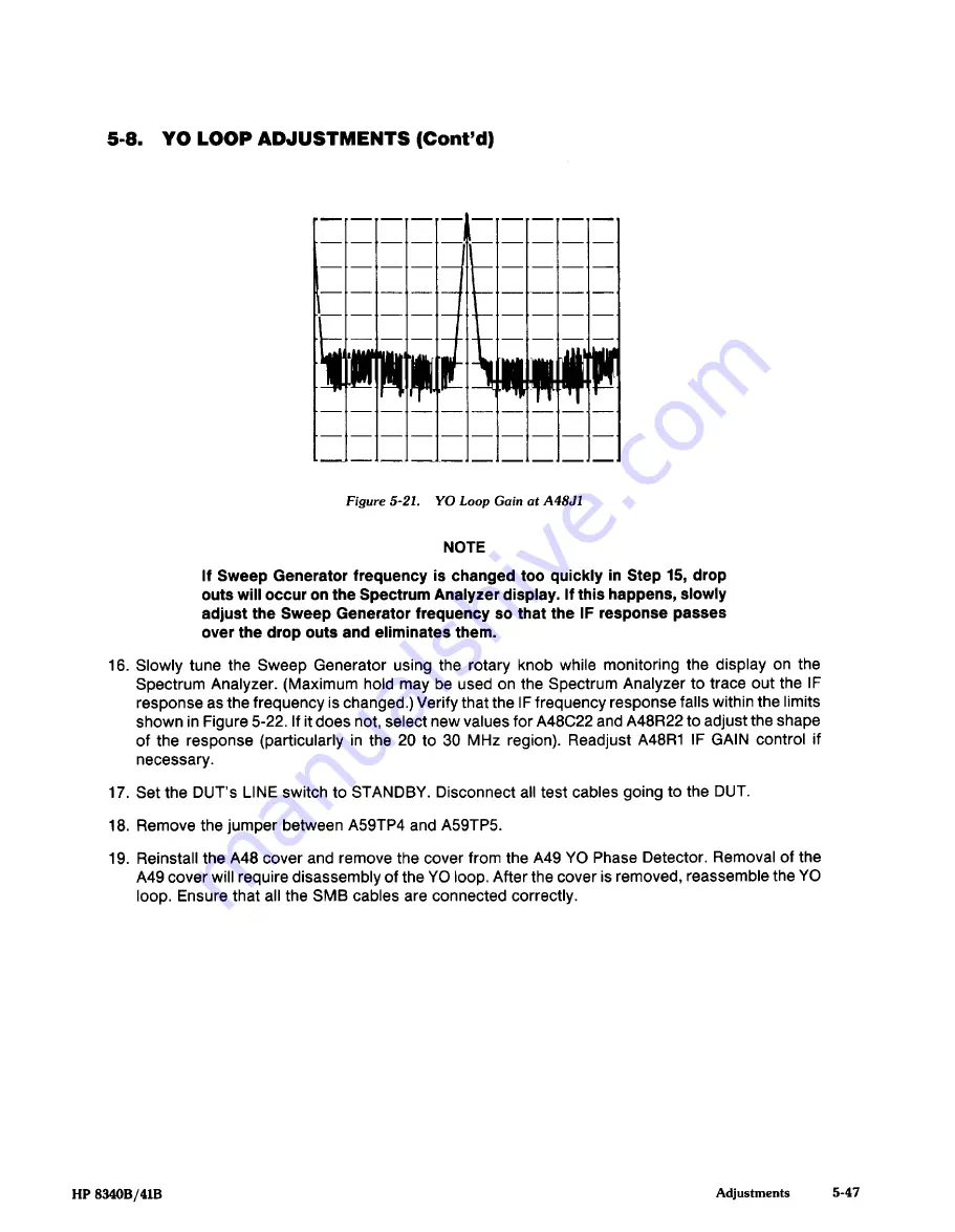
Figure 5-21.
YO Loop Gain at A48J1
HP 8340B/41B
Adjustments
5-47


