4-4.
SWEPT FREQUENCY ACCURACY
Specification
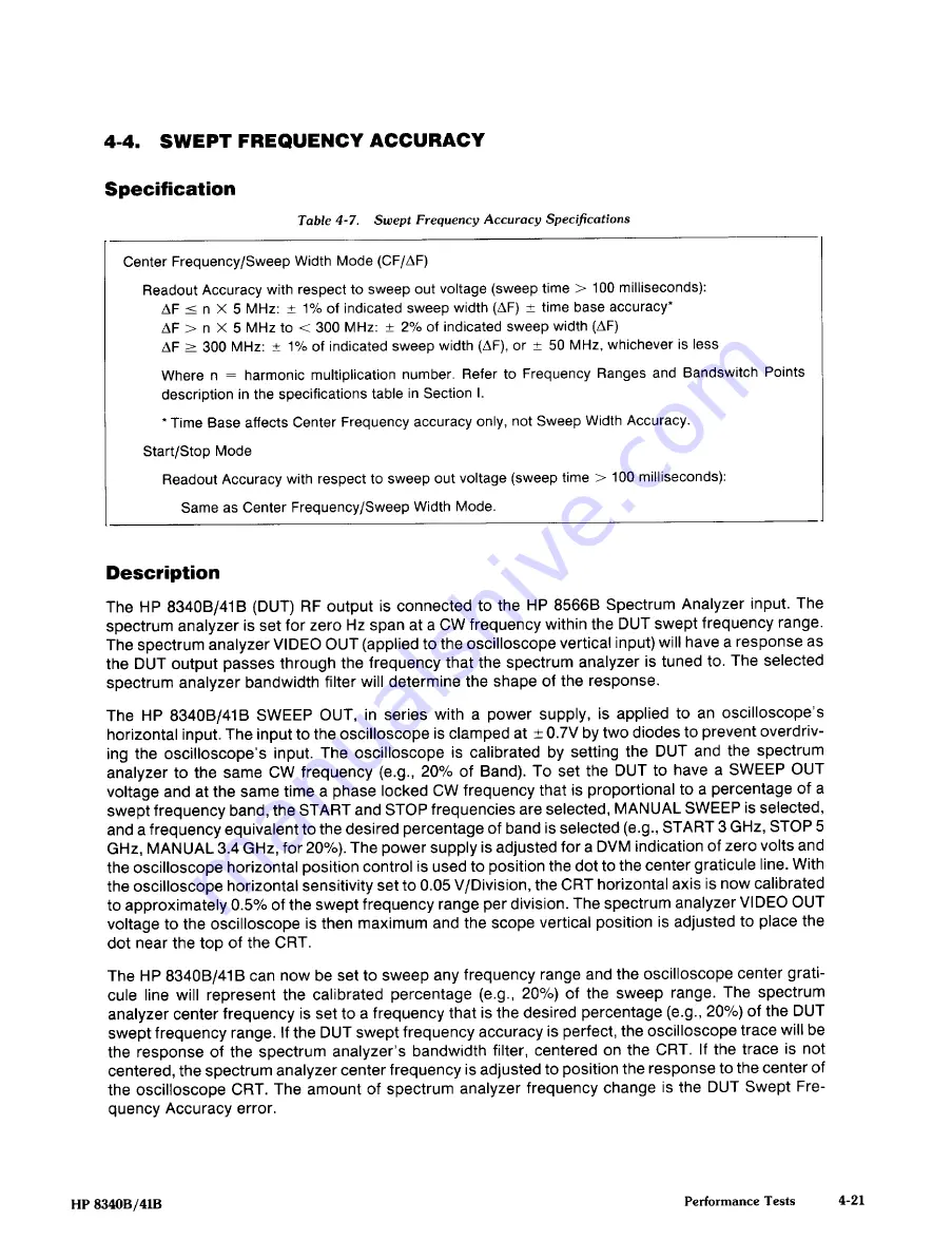
Table 4-7.
Swept Frequency Accuracy Specifications
Description
The HP 8340B/41B (DUT) RF output is connected to the HP 85668 Spectrum Analyzer input. The
spectrum analyzer is set for zero Hz span at a CW frequency
within
the DUT swept frequency range.
The spectrum analyzer VIDEO OUT (applied to the oscilloscope vertical input) will have a response as
the DUT output passes through the frequency that the spectrum analyzer is tuned to. The selected
spectrum analyzer bandwidth filter will determine the
shape of the response.
The HP 8340B/41B SWEEP OUT, in series with a power supply, is applied to an oscilloscope’s
horizontal input. The
input to the oscilloscope
is clamped at ~ 0.7V by two diodes to prevent overdriv-
ing the oscilloscope’s input. The oscilloscope is calibrated by setting the DUT and the spectrum
analyzer to the same CW frequency (e.g., 20% of Band). To set the DUT to have a SWEEP OUT
voltage and at the same time a phase locked CW frequency that is proportional to a percentage of a
swept frequency band, the START and STOP frequencies are selected, MANUAL SWEEP is selected,
and a frequency equivalent to the desired percentage of band is selected (e.g., START 3 GHz, STOP 5
GHz, MANUAL 3.4 GHz, for
20~/o).
The power supply is adjusted for a DVM indication of zero volts and
the oscilloscope horizontal position control is used to position the dot to the center graticule line. With
the oscilloscope horizontal sensitivity set to 0.05 V/Division, the CRT horizontal axis is now calibrated
to approximately 0.5% of the swept frequency range per division. The spectrum analyzer VIDEO OUT
voltage to the oscilloscope is then maximum and the scope vertical position is adjusted to place the
dot near the top of the CRT.
The HP 8340B/41B can now be set to sweep any frequency range and the oscilloscope center grati-
cule line will represent the calibrated percentage (e.g., 20%) of the sweep range. The spectrum
analyzer center frequency is set to a frequency that is the desired percentage (e.g., 200/0) of the DUT
swept frequency range. If the DUT swept frequency accuracy
is perfect, the oscilloscope trace will be
the response of the spectrum analyzer’s bandwidth filter, centered on the CRT. If the trace is not
centered, the spectrum analyzer center frequency is adjusted to positionthe response to the center of
the oscilloscope CRT. The amount of spectrum analyzer frequency change is the DUT Swept Fre-
quency Accuracy error.
Center Frequency/Sweep Width Mode (CF/AF)
Readout Accuracy with respect to sweep out voltage (sweep time> 100 milliseconds):
AF
=
n X 5 MHz:
±
1% of indicated sweep width (AF) ~ time base accuracy0
AF> n X 5 MHz to <300 MHz:
±
20/o
of indicated sweep width (AF)
AF
=
300 MHz:
±
1% of indicated sweep width (AF), or
t
50 MHz, whichever is less
Where n
=
harmonic multiplication number. Refer to Frequency Ranges and Bandswitch Points
description in the specifications table in Section I.
*
Time Base affects Center Frequency accuracy only, not Sweep Width Accuracy.
Start/Stop Mode
Readout Accuracy with respect to sweep out voltage (sweep time
>
100 milliseconds):
Same as Center Frequency/Sweep Width Mode.
HP 8340B/41B
Performance Tests
4-21


