2.
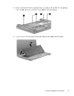
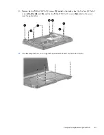
Remove two Phillips PM2.5×3.0 broadhead black screws
(1)
, one Phillips PM2.5×3.0 broadhead
silver screw
(2)
, and two Torx M2.5×6.0 screws
(3)
that secure the keyboard.
3.
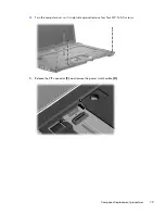
Turn the unit over, lift the top edge of the keyboard
(1)
and slide it
(2)
towards the display.
Component replacement procedures
75
Содержание 625
Страница 1: ...Compaq 325 and 326 Notebook PCs HP 425 and 625 Notebook PCs Maintenance and Service Guide ...
Страница 4: ...iv Safety warning notice ...
Страница 27: ...Bottom components NOTE Refer to the illustration that most closely matches your computer Bottom components 19 ...
Страница 33: ...Computer major components Computer major components 25 ...
Страница 154: ...RJ 11 modem Pin Signal 1 Unused 2 Tip 3 Ring 4 Unused 5 Unused 6 Unused 146 Chapter 8 Connector pin assignments ...

