
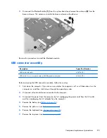


7.
Pull the extender out
(2)
of the system board and lift it from the base enclosure.
8.
Release the RJ-11 cable from the cable routing area, lift the connector from the base enclosure
(1)
,
and disconnect the cable
(2)
from the system board.
9.
Disconnect the main battery cable
(3)
from the bottom of the system board.
10.
Lift the system board at an angle
(4)
and slide it
(5)
out of the base enclosure.
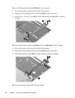
Remove the system board on
35.6-cm
(14.0-in) or
33.8-cm
(13.3-in) computers:
1.
Position the computer with the front toward you.
98
Chapter 4 Removal and replacement procedures
Содержание 625
Страница 1: ...Compaq 325 and 326 Notebook PCs HP 425 and 625 Notebook PCs Maintenance and Service Guide ...
Страница 4: ...iv Safety warning notice ...
Страница 27: ...Bottom components NOTE Refer to the illustration that most closely matches your computer Bottom components 19 ...
Страница 33: ...Computer major components Computer major components 25 ...
Страница 154: ...RJ 11 modem Pin Signal 1 Unused 2 Tip 3 Ring 4 Unused 5 Unused 6 Unused 146 Chapter 8 Connector pin assignments ...