


3.
Disconnect the power from the computer by first unplugging the power cord from the AC outlet
and then unplugging the AC adapter from the computer.
4.
Remove the battery (see
Battery on page 51
).
5.
Remove the service door (see
Service door on page 52
).
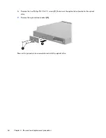
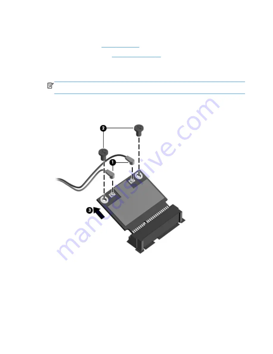
Remove the WLAN module:
1.
Disconnect the WLAN antenna cables
(1)
from the terminals on the WLAN module.
NOTE:
The black WLAN antenna cable is connected to the WLAN module “Main” terminal. The
white WLAN antenna cable is connected to the WLAN module “Aux” terminal.
2.
Remove the two Phillips PM2.0×2.5 screws
(2)
that secure the WLAN module to the computer.
(The edge of the module opposite the slot rises away from the computer.)
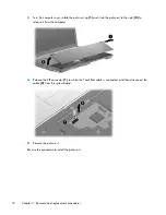
3.
Remove the WLAN module
(3)
by pulling the module away from the slot at an angle.
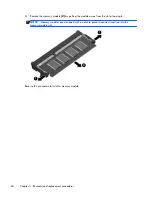
Reverse this procedure to install the WLAN module.
62
Chapter 4 Removal and replacement procedures
Содержание 625
Страница 1: ...Compaq 325 and 326 Notebook PCs HP 425 and 625 Notebook PCs Maintenance and Service Guide ...
Страница 4: ...iv Safety warning notice ...
Страница 27: ...Bottom components NOTE Refer to the illustration that most closely matches your computer Bottom components 19 ...
Страница 33: ...Computer major components Computer major components 25 ...
Страница 154: ...RJ 11 modem Pin Signal 1 Unused 2 Tip 3 Ring 4 Unused 5 Unused 6 Unused 146 Chapter 8 Connector pin assignments ...