


3.
Disconnect the power from the computer by first unplugging the power cord from the AC outlet
and then unplugging the AC adapter from the computer.
4.
Remove the battery (see
Battery on page 51
).
5.
Remove the service door (see
Service door on page 52
).
6.
Remove the palm rest (see
Palm rest on page 70
).
7.
Remove the keyboard (see
Keyboard on page 73
).
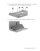
8.
Remove the top cover (see
Top cover on page 77
).
Remove the display on
39.6-cm
(15.6-in) computers:
1.
Orient the computer in its normal position, face up with the display open as far as it will
comfortably go.
CAUTION:
Support the display assembly when removing the retaining screws. Failure to
support the display assembly can result in damage to the display assembly and other computer
components.
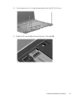
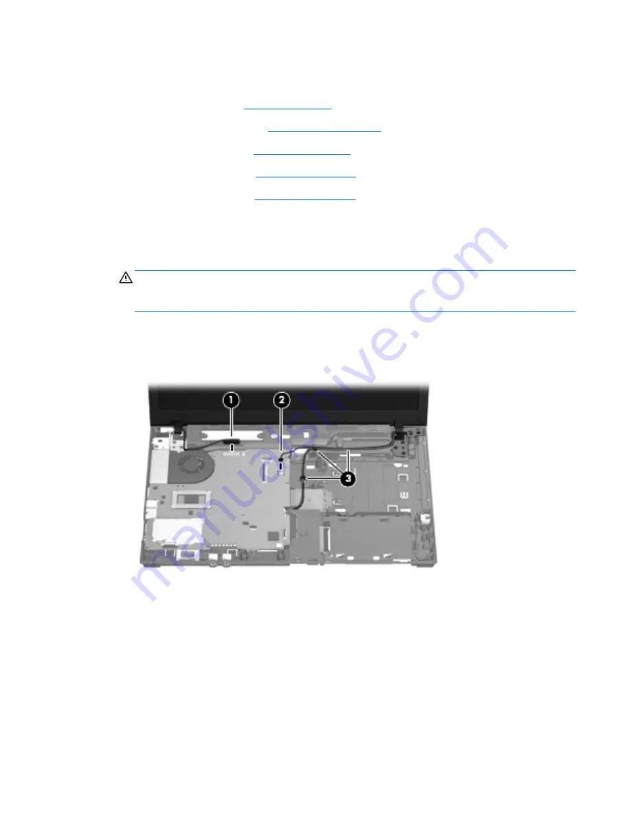
2.
Disconnect the display cable
(1)
and the microphone cable
(2)
from the system board.
3.
Release the WLAN cables from the cable run
(3)
, being careful when pulling them through the
opening near the hard drive.
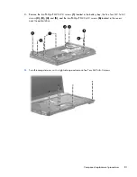
4.
Remove eight Torx M2.5×6.0 screws
(1)
that secure the display to the base enclosure. Be careful
of the grounding cable
(2)
that is secured by one of the hinge retaining screws.
Component replacement procedures
89
Содержание 625
Страница 1: ...Compaq 325 and 326 Notebook PCs HP 425 and 625 Notebook PCs Maintenance and Service Guide ...
Страница 4: ...iv Safety warning notice ...
Страница 27: ...Bottom components NOTE Refer to the illustration that most closely matches your computer Bottom components 19 ...
Страница 33: ...Computer major components Computer major components 25 ...
Страница 154: ...RJ 11 modem Pin Signal 1 Unused 2 Tip 3 Ring 4 Unused 5 Unused 6 Unused 146 Chapter 8 Connector pin assignments ...