


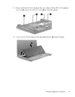


3.
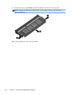
Raise the end of the heat sink
(3)
to free it from the system board components and then remove
the heat sink
(4)
from the system board.
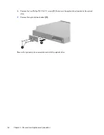
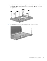
Remove the heat sink on computers with discrete graphics subsystems:
1.
Position the computer right-side up with the front facing you.
2.
Following the numbered sequence stamped into the heat sink, loosen the captive screws
(1)
and
(2)
around the processor.
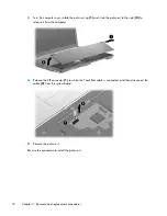
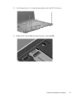
3.
Lift the heat sink
(3)
from the system board.
Following the numbered sequence stamped into the heat sink, reverse the above procedure to install the
heat sink.
Component replacement procedures
67
Содержание 625
Страница 1: ...Compaq 325 and 326 Notebook PCs HP 425 and 625 Notebook PCs Maintenance and Service Guide ...
Страница 4: ...iv Safety warning notice ...
Страница 27: ...Bottom components NOTE Refer to the illustration that most closely matches your computer Bottom components 19 ...
Страница 33: ...Computer major components Computer major components 25 ...
Страница 154: ...RJ 11 modem Pin Signal 1 Unused 2 Tip 3 Ring 4 Unused 5 Unused 6 Unused 146 Chapter 8 Connector pin assignments ...