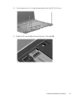


6.
Lift the display panel up and out the housing
(2)
.
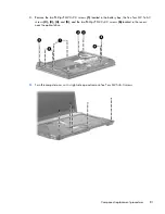
Remove the display hinges from a
39.6-cm
(15.6-in) computer:
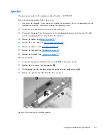
1.
Remove the eight Phillips PM2.0×3.0 screws
(1)
that secure the display hinges to the display
panel.
2.
Remove the display hinges
(2)
by pulling them away from the display panel. The left and right
display hinges are available in the Hinge Kit, spare part number 605769-001.
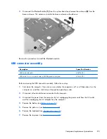
Remove the display hinges from
35.6-cm
(14.0-in) or
33.8-cm
(13.3-in) computers:
1.
Remove the six Phillips PM2.0×3.0 screws
(1)
that secure the display hinges to the display panel
Component replacement procedures
93
Содержание 625
Страница 1: ...Compaq 325 and 326 Notebook PCs HP 425 and 625 Notebook PCs Maintenance and Service Guide ...
Страница 4: ...iv Safety warning notice ...
Страница 27: ...Bottom components NOTE Refer to the illustration that most closely matches your computer Bottom components 19 ...
Страница 33: ...Computer major components Computer major components 25 ...
Страница 154: ...RJ 11 modem Pin Signal 1 Unused 2 Tip 3 Ring 4 Unused 5 Unused 6 Unused 146 Chapter 8 Connector pin assignments ...


