


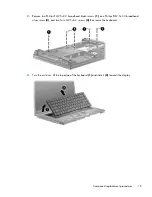


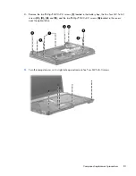


3.
Remove the two Phillips PM2.0×2.0 screws
(1)
located in the battery bay, the five Torx M2.5×6.0
screws
(2), (3), (4)
, and
(5)
, and the two Phillips PM2.0×3.0 screws
(6)
located in the recess
near the optical drive.
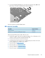
4.
Turn the computer over so it is right-side up and remove five Torx M2.5×6.0 screws.
Component replacement procedures
81
Содержание 625
Страница 1: ...Compaq 325 and 326 Notebook PCs HP 425 and 625 Notebook PCs Maintenance and Service Guide ...
Страница 4: ...iv Safety warning notice ...
Страница 27: ...Bottom components NOTE Refer to the illustration that most closely matches your computer Bottom components 19 ...
Страница 33: ...Computer major components Computer major components 25 ...
Страница 154: ...RJ 11 modem Pin Signal 1 Unused 2 Tip 3 Ring 4 Unused 5 Unused 6 Unused 146 Chapter 8 Connector pin assignments ...