


Chapter 4 - Operation
To set monitor resolution
1. Verify that the monitors are physically attached to at least the highest and lowest video channels.
2. Select Start > Settings > Control Panel.
3. Double-click Display and select the Change display settings option.
The Screen Resolution page appears.
4. Arrange the display according to your physical orientation.
5. Click Apply and then click OK.
4.2
Network connections
Each Honeywell-configured platform must be connected to an ETHERNET network.
l
l
l
l
l
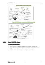
Z-Console connection to the LCN coax cable
l
Connecting LCN coax to LCN MAU in Z-Console
4.2.1
Ethernet network
ETHERNET 10/100/1000 Base T connection is the standard connection used on the Honeywell-
configured platform. Dual NIC option is available for FTE. The on-board Ethernet connection must be
disabled in the System BIOS prior to installation of the Dual Port Broadcom 5720 NIC adapter. The
Network Controller Model Number is as follows.
NE-NICS04
Broadcom Dual Port X1 GIGABIT NIC adapter
4.2.2
Local Control Network
The connection to the LCN Network is made via the LCNP4e / LCNP4e2 mid-size Local Control
Network Processor card model no. TP-LCNP04 / TP-LCNP05. This card provides the communication
path for the T5810XL to other LCN modules. The LCNP4E / TP-LCNP05 consists of a PCI Express 3.3
Volt LCNP4e / LCNP4e2 full height and half length size card, a MAU cable and the LCN MAU (Media
Access Unit).
Set the LCN node address as required. If the LCN address is not known, then the node address should
be set to zero (0). Setting the address to zero (0) allows the node to be connected to the LCN without
the risk of an address conflict with some other live node in your network segment. This is consistent with
the current LCN standard procedure. The following model numbers are available for the Local Control
Network Processors:
TP-LCNP04
LCNP4E
TP-LCNP05
LCNP4e2
- 64 -