Honeywell 2MLL-PMEA Скачать руководство пользователя страница 35

Chapter 5 Communication Program 


Pnet  I/F  Module  2MLL-PSRA,  2MLL-PMEA,  2MLL-PMEB  User

’s  Guide 


      R240 


Honeywell 

                      January  2019 


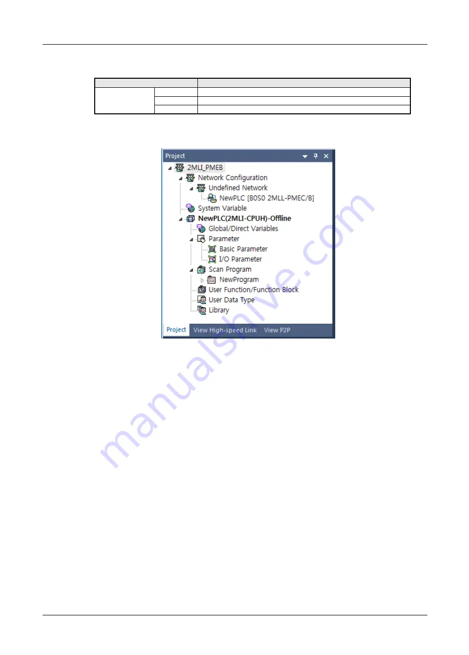
Pnet I/F module Off-line registration on base 0, slot 2 is as follow 


Classification 

Description 

Communication 

module setting 

Type 

Pnet I/F module   

Base 

Base no. of mounted module 

Slot 

Slot no. of mounted module


[Table 5.2.1] Communication module setting contents 


Registration PMEB module on base 0, slot 2 


[Figure 5.2.7] Registration screen 

Содержание 2MLL-PMEA

Страница 1: ...Honeywell Process Solutions Profibus DP Pnet Module 2MLL PMEB PSRA PSEA User s Guide R240 January 2018 Release 240 Honeywell ...

Страница 2: ... and makes no express warranties except as may be stated in its written agreement with and for its customers In no event is Honeywell liable to anyone for any indirect special or consequential damages The information and specifications in this document are subject to change without notice Honeywell PlantScape Experion PKS and TotalPlant are registered trademarks of Honeywell International Inc Othe...

Страница 3: ...ration tool added Automatic Network Scan modified Ch 9 1 1 2MLL PSRA added Ch 1 3 3 V 2 1 11 05 How to enable link through flag added Ch 5 2 3 V 2 2 11 06 Performance specifications added Max number of modules per node 24 Modules Ch 2 2 V2 3 14 11 SoftMaster V4 0 UI Updated V2 4 16 03 Add 2MLL PMEB PROFIBUS DPv1 setting P2P communication setting SoftMaster UI updated 2MLL PMEB contents P2P setting...

Страница 4: ... MLC Instructions Programming User s Manual User s manual for programming to explain how to use instructions that are used PLC system with 2MLK MLM MLC CPU 2MLI 2MLR MLI Instructions Programming User s Manual User s manual for programming to explain how to use instructions that are used PLC system with 2MLI 2MLR MLI CPU 2MLK CPU User s Manual 2MLK CPUA CPUE CPUH CPUS CPUU 2MLK CPUA CPUE CPUH CPUS ...

Страница 5: ...hecking the version 1 5 Chapter 2 Specifications 2 1 General Specifications 2 1 2 2 Performance Specifications 2 2 2 3 Structure Characteristics 2 3 2 3 1 Structure of Pnet I F module 2 3 2 4 Cable Specifications 2 6 2 4 1 Cable specifications of Belden network 2 6 Chapter 3 Installation and Test Operation 3 1 Precautions for Installation 3 1 3 1 1 Precautions for Installation 3 1 3 2 From Setting...

Страница 6: ...gh Speed Link parameter and setup 5 8 5 2 4 Setting P2P Parameter 5 11 Chapter 6 SyCon Setting 6 1 Introduction 6 1 6 1 1 Main functions 6 1 6 1 2 Characteristics 6 1 6 2 Installation 6 1 6 2 1 System requirements 6 1 6 2 2 Software installation 6 2 6 3 Communication settings in SyCon 6 8 6 3 1 Initial screen 6 8 6 3 2 Composition of menu 6 9 6 3 3 New file 6 11 6 3 4 Master selection 6 12 6 3 5 S...

Страница 7: ...ownload and upload Network Configuration 7 17 7 5 1 Download Network Settings 7 17 7 5 2 Upload Network Settings 7 19 7 6 Diagnosis function 7 20 7 6 1 Start Stop Communication 7 20 7 6 2 Debug mode Start Stop Debug Mode Device Diagnostics 7 20 7 6 3 Live List 7 22 7 6 4 Automatic Network Scan 7 23 7 6 5 I O Data Monitoring 7 24 7 6 6 Disconnection Report 7 25 7 6 7 Master information Device Infor...

Страница 8: ... and Management by LED Status 11 1 11 2 System Diagnosis of SOFTMASTER 11 2 11 2 1 Information on communication module 11 2 11 2 2 High speed link 11 3 11 2 3 Log 11 3 11 2 4 Auto scan 11 4 11 3 Diagnosis of Communication Module through SOFTMASTER 11 5 11 4 Troubleshooting 11 6 11 4 1 SyCon abnormal connection 11 6 11 4 2 SOFTMASTER abnormal connection 11 7 11 4 3 Abnormal connection with slave mo...

Страница 9: ...I F Module 2MLL PSRA 2MLL PMEA 2MLL PMEB User s Guide R240 Honeywell January 2019 Appendix A 1 Terminology A 1 A 2 List of Flags A 3 A 2 1 High speed link flags A 3 A 2 2 Link devices N A 6 A 3 Dimensions A 8 ...

Страница 10: ... used to control the communication and to configure the network easily Pnet I F module is a module to control the field bus with Twisted Shielded Pair Copper Cable applied 1 2 Characteristics ML200 Pnet I F module has the characteristics as follows Conforms to the international standard of EN 50170 Supports Auto Baud Rate Detect Supports Sync Freeze mode Max input data 244 Bytes Slave Max output d...

Страница 11: ... Asynchronous data exchange between the PC or PLC and the slave device integration of EDD and FDT fail safe communication alarm 3 DP V2 supports broadcast clock synchronization and time stamp HART upload download redundancy 1 3 2 Available number by CPU You can mount up to 12 Pnet I F module If possible mount the module in the basic base for best performance of the communication module The followi...

Страница 12: ... 47060048 TR output 16 0 5A Source MPL TR4C 47060049 TR output 32 0 5A Source MPL RY2C 47060051 Relay output 16 MPL DT4C 47060050 DC input16 TR output 16 MPL TR2B 47060059 TR output 16 0 5A Source Fixed type 9 pin communication connector MPL TR4B 47060058 TR output 32 0 5A Source MPL DT4B 47060060 DC input16 TR output 16 MPL TR2A1 47060084 TR output 16 0 5A Sink MPL TR4A1 47060076 TR output 32 0 5...

Страница 13: ... V2 0 Configuration tool for 2MLL PMEA N Configurator V3 1 x or later Configuration tool for 2MLL PMEB C Note 1 You can download the above software from our web site In case Internet is available visit the nearest distributor and get the installation CD Web site address http www lsis com 2 You can program the SOFTMASTER through the RS 232C port and USB of the CPU module For the cable refer to wiri...

Страница 14: ...OFTMASTER initial screen 1 4 3 Checking the version Before using the Pnet I F module check the version of the module 1 Check through the SOFTMASTER This is method reading the communication module information through online connection If it is under normal interface with the CPU you can get the information as follows a Execute the SOFTMASTER b Connect to the CPU through Connect on the Online menu c...

Страница 15: ... 2019 Figure 1 4 2 Checking the version of the module through the SOFTMASTER 2 Check through the case label of the product The module information is attached at the external case every communication modules In case online connection is not available take a module apart and check the label in the module case ...

Страница 16: ...lectrostatic discharge Voltage 4kV Contact discharge IEC61131 2 IEC61000 4 2 Radiated electromagnetic field noise 80 1000 MHz 10V m IEC61131 2 IEC61000 4 3 Fast transient Burst noise Classific ation Power supply Digital Analog Input Output Communication Interface IEC61131 2 IEC61000 4 4 Voltage 2kV 1kV 8 Operation ambience Free from corrosive gases and excessive dust 9 Altitude Less than 2 000m 10...

Страница 17: ... number of stations per segment 32 including master repeater Max number of modules per node 24 modules Cable used Electric twist shielded pair cable Max communication size 10 KBytes Max size per slave 244 bytes Max number of units to be installed 2MLK CPUH 2MLI CPUH 2MLK CPUS CPUA CPUE 2MLR CPUH T CPUH F CPUH S 24 24 24 Installation Position 2MLK CPUH 2MLI CPUU 2MLK CPUS CPUA CPUE 2MLR CPUH T CPUH...

Страница 18: ...atus when High speed link is enabled Blink Stand by Communication break status between Pnet I F module and slave when downloading by Sycon Off Error High speed link service error occurred when High speed link is enabled P RUN Blink Stop Stop status of communication status between Pnet I F module and slave module On Run Run status of Communication between Pnet I F module and slave module STAT On No...

Страница 19: ...ation Normal communication between the Pnet I F module and slave Blink Under communication Clear communication between the Pnet I F module and slave I O data 0 On Communication stop Communication stop status between the Pnet I F module and slave STATUS On Error System error Blink Auto scan System auto scan mode Off Normal System normal ERR On Error Bus error line short different communication spee...

Страница 20: ...ble status P2P On Normal Normal P2P communication status Blink Standby Stop communication status downloading Parameter in P2P enable Off Error P2P disable status P RUN On Normal Normal communication Off Error Communication is stopped STATUS On Error System error Off Normal Normal communication ERR On Error All slaves are eliminated Blink Error Some slaves are eliminated Off Normal Normal CFG On Er...

Страница 21: ...freq 100kHz Capacity 30 pF m 60 pF m Resistance 110 Ω Conductor Area 0 34 mm2 22 AWG 0 22 mm2 24 AWG Table 2 4 1 Cable specification Baud Rate Kbit s 9 6 19 2 31 25 45 45 93 75 187 5 500 1500 3000 6000 12000 Cable Type A 1200 1200 1200 1200 1200 1200 400 200 100 100 100 Cable Type B 1200 1200 1200 1200 1200 600 200 70 Table 2 4 2 Communication distance by cable and baud rate Remark 1 The profibus ...

Страница 22: ...tor the module will be installed on and any damage on the connector pin of the module 4 All the communication modules can be installed on the basic base the expansion base For the number of available expansion base by CPU refer to the following table Item 2MLK 2MLI 2MLR 2MLK CPUH CPUU 2MLK CPUA CPUS CPUSN 2MLK CPUHN CPUUN 2MLK CPUE 2MLI CPUUN 2MLI CPUU 2MLI CPUH 2MLI CPUS 2MLI CPUE 2MLR CPUH T CPU...

Страница 23: ...e configuration through SyCon or N Configurator Specify the module to be configured as Pnet I F master module and download it Download High speed link P2P parameters Set how to connection with Online Connection Online Diagnosis I O information I O Sync Open the High speed Link block setting tab Execute Online Communication module setting Config Upload at High speed Link block tab Set the High spee...

Страница 24: ...nstalled shall be within 32 including master and repeater for 1 segment 4 The shielded line of the cable shall be in contact with the shielded area of the connector 5 The cable is generally recommended to be installed at the end of the slave diverged from the master 6 If the cable is used at the object car use the extended line 7 Communication cable shall be installed at least 10cm away from the p...

Страница 25: ...ctor structure and wiring method 1 Input Line green line is connected to A1 red line is connected to B1 2 Output line green line is connected to A2 red line is connected to B2 3 Connect shield to clamp of shield 4 In case of installing the connector at terminal install the cable at A1 B1 Connector structure Cable structure Cable wiring method ...

Страница 26: ...s not have station no The extended segment having no station is available 3 Shield shall be connected to the housing of connector 4 Use the special connector having the inductor inside 5 Spur Line is not allowed to use 6 If the ground potential difference between stations is big a great amount of current may flow through the shield In this case install the cable to make the ground potential differ...

Страница 27: ...ions also shall be different from each other to use High speed link service 2 Use the communication cable as specified only If not serious error may occur to communication 3 Check communication cable if disconnected or shorted prior to installation 4 Tighten up communication cable connector until connected firmly If cable connection is unstable serious error may occur to communication 5 If remote ...

Страница 28: ...em Configuration of Network 4 1 1 ML200 Pnet module and Smart I O Communication system of Pnet I F modules is as shown below Set the Pnet I F module as master in system and the others have to set as slave module To connect LS inverter Pnet I F option module have to install applicable product then it will be communicate Figure 4 1 ML200 Pnet Smart I O diagram ...

Страница 29: ...used with another company product GSD file provided by the maker is needed After GSD file is copied to GSD folder of Pnet configuration software tool SYCON N Configurator and then if you use Pnet configuration software tool SYCON N Configurator you can configure the slave modules in the network automatically Figure 4 1 2 ML200 Pnet Composite system Diagram Sensor ...

Страница 30: ... sec based on the communication details It is easy to use because communication with destination station is available only through simple parameters setting And it is also useful for periodic process of lots of data at a time thanks to high processing speed of the internal data 2 P2P P2P is the communication method between ML200 PLC communication module and slave module It can be used to read writ...

Страница 31: ...tion is uploaded and then download the specified parameters onto CPU for application which is available through the SoftMaster 5 2 1 Setting PLC type To connect the SoftMaster to the PLC you have to set the PLC type Create the new project by selecting File New File On the new project menu input the project name project type and PLC type as shown below Fig 5 2 1 is initial screen of the SoftMaster ...

Страница 32: ... Selecting the directory to save the project PLC Series Selecting the PLC series 2MLK ML50 2MLI 2MLR CPU kind 2MLK 2MLK CPUA CPUE CPUH CPUS CPUU ML50 ML50 MLMS MLCH MLIH MLIE 2MLI 2MLI CPUU CPUU D CPUH CPUE CPUS 2MLR 2MLR CPUH T 2MLR CPUH F Project comment Writing the comment about the project There are 4 types of PLC 2MLK ML50 2MLI and 2MLR For detail on the CPU refer to CPU manual Here we select...

Страница 33: ...r the basic setting of the communication module in the SoftMaster you have to register the communication module at the applicable base slot position of Standard setting window You can register the communication in the both ON OFF status 1 Registration in the offline status If you want to register the communication without connection select the base and slot of standard setting window Registration ...

Страница 34: ...ser s Guide R240 Honeywell January 2019 Figure 5 2 4 Communication module menu selecting b Click Add module in Select Communication Module window Figure 5 2 5 Add module c Select the type base and slot in Communication Module Settings window Figure 5 2 6 Communication module setting ...

Страница 35: ... I F module Off line registration on base 0 slot 2 is as follow Classification Description Communication module setting Type Pnet I F module Base Base no of mounted module Slot Slot no of mounted module Table 5 2 1 Communication module setting contents Registration PMEB module on base 0 slot 2 Figure 5 2 7 Registration screen ...

Страница 36: ...module After connection if you select Online Diagnosis I O Information then click I O Sync it searches all communication module and register them automatically PLC should be STOP status for I O Sync Figure 5 2 6 Read IO Information In case Pnet is installed at the base 0 slot 10 it searches and registers as follows Figure 5 2 7 Basic setting and Communication module Settings screen ...

Страница 37: ... Link parameter and setup 1 Screen of communication module specified Figure 5 2 9 Communication Module Settings 2 Uploading a configuration tool SyCon or N Configurator With the mouse cursor positioned on High speed link1 select Online Communication module setting Config Upload Dnet Pnet Figure 5 2 10 Config data Upload from SyCon or N Congurator ...

Страница 38: ...ave module to master module Read area Master module Slave module 2MLK Area to set the start address of device used for Sending Setting device P M K F T C U Z L N D R ZR 2MLI Area to set the start address of device used for Sending Setting device A M I Q R W F K L N U Save area Slave module Master module 2MLK Area to set the start address of device used for Receiving Setting device P M K F T C U Z ...

Страница 39: ...F Module 2MLL PSRA 2MLL PMEA 2MLL PMEB User s Guide R240 Honeywell January 2019 5 High speed link parameters download Figure 5 2 12 High speed link parameters download 6 Enabling the Link Figure 5 2 13 Link Enable of High speed link parameters ...

Страница 40: ...communication module setting 2 P2P parameter setting Item Description P2P function Write read diagnostic Condition flag Condition flag Data type 1 Data type No of variable 1 No of variable Destination station Check destination station No of destination station Destination station Setting Read area Sending data area Save area Save area of receiving data Data size Sending Receiving data size 1 isn t...

Страница 41: ...ation Program 12 Pnet I F Module 2MLL PSRA 2MLL PMEA 2MLL PMEB User s Guide R240 Honeywell January 2019 5 Download P2P parameter Figure 5 2 16 P2P parameter download 6 Enable link Figure 5 2 17 Enable link P2P parameter ...

Страница 42: ... HS link 2 enable disable current state _HS3_ENABLE_STATE BIT F09602 HS link 3 enable disable current state _HS4_ENABLE_STATE BIT F09603 HS link 4 enable disable current state _HS5_ENABLE_STATE BIT F09604 HS link 5 enable disable current state _HS6_ENABLE_STATE BIT F09605 HS link 6 enable disable current state _HS7_ENABLE_STATE BIT F09606 HS link 7 enable disable current state _HS8_ENABLE_STATE BI...

Страница 43: ...nt state _P2P8_ENABLE_STATE BIT F09627 P2P8 enable disable current state _P2P1_REQ BIT F10320 P2P1 enable disable request _P2P2_REQ BIT F10321 P2P2 enable disable request _P2P3_REQ BIT F10322 P2P3 enable disable request _P2P4_REQ BIT F10323 P2P4 enable disable request _P2P5_REQ BIT F10324 P2P5 enable disable request _P2P6_REQ BIT F10325 P2P6 enable disable request _P2P7_REQ BIT F10326 P2P7 enable ...

Страница 44: ...uary 2019 7 Read a Connect to CPU b After connected select On line and Read Parameter to display the screen as shown in Figure 5 2 16 and then check the applicable parameters and click OK Figure 5 2 14 Read screen c Reads previously specified values for the parameters checked 8 View Tree by Transmission Reception ...

Страница 45: ...Chapter 5 Communication Program 16 Pnet I F Module 2MLL PSRA 2MLL PMEA 2MLL PMEB User s Guide R240 Honeywell January 2019 ...

Страница 46: ...Debugger Global State Field User data Send I O monitor I O monitor Documentation Print Print out the Configuration 6 1 2 Characteristics SyCon is a Global Fieldbus Configurator SyCon executes the configuration through a standardized file SyCon has a diagnosis function 6 2 Installation 6 2 1 System requirements PC 486 or higher Windows 95 98 ME NT 2000 XP or later version Hard disc with 80MB or mor...

Страница 47: ... is inserted into CD ROM Execute Autorun exe 2 Select System installation and execute 1 Do you want to install the System Configurator SyCon Yes 2 Do you want to install the SyCon integrated OPC Server No 3 Do you want to the Stand Alone OPC Server Busserver No 4 Do you have a License code Yes 5 Select Language Next Select System Installation Select here ...

Страница 48: ...yCon Setting 3 Pnet I F Module 2MLL PSRA 2MLL PMEA 2MLL PMEB User s Guide R240 Honeywell January 2019 3 License Agreement Select I agree 4 Program Registration Input License code F90BF4B3E874 Select OK Select Yes ...

Страница 49: ...Chapter 6 SyCon Setting 4 Pnet I F Module 2MLL PSRA 2MLL PMEA 2MLL PMEB User s Guide R240 Honeywell January 2019 5 Configuration Setup Select Next ...

Страница 50: ...dule 2MLL PSRA 2MLL PMEA 2MLL PMEB User s Guide R240 Honeywell January 2019 1 Components Select Next 2 Program Folder Select Next Select the destination folder to install Display minimum Disk Space required of PC Select Network to install ...

Страница 51: ...Chapter 6 SyCon Setting 6 Pnet I F Module 2MLL PSRA 2MLL PMEA 2MLL PMEB User s Guide R240 Honeywell January 2019 3 Setup complete 6 Installed contents 1 Installed file ...

Страница 52: ...ing 7 Pnet I F Module 2MLL PSRA 2MLL PMEA 2MLL PMEB User s Guide R240 Honeywell January 2019 2 Contents of Folder Destination C Program Files Honeywell SyCon 3 GSD files for Profibus GSD files are generated as shown below ...

Страница 53: ... 6 SyCon Setting 8 Pnet I F Module 2MLL PSRA 2MLL PMEA 2MLL PMEB User s Guide R240 Honeywell January 2019 6 3 Communication Settings in SyCon 6 3 1 Initial screen Network Edit Menu Icon Status Menu Icon Status ...

Страница 54: ... file GSD DBM Import DBM extension file CSV Import CSV extension file Print Print Print Preview Preview of print Print Setup Setup of print Recent File Display of recent file list Exit Exit SyCon Editer Cut Cutting Copy copying Paste Pasting Delete Deleting Replace Replace View Device Table Display of device name ID and Type Address Table Display of slave module address and Size of Input Output Lo...

Страница 55: ... Network Scan Setting the network automatically Get Device Attribute Set Device Attribute Start Communication Run the communication Stop Communication stop the communication Device Info Display of the day of manufacture and Serial number Activate Driver To register the unregistered device Read project Information Information of project Settings Device Assignment Setup the way of communication with...

Страница 56: ...Honeywell January 2019 6 3 3 New file 1 Selection of Fieldbus 2 The composition of picture 3 Master selection Master type GSD File Name Master name ML200 2MLL PMEA HIL_069E COM C DPM GM MK G3L PUEA G4L PUEA G6L PUEA HIL_7065 COM DPM PKV20 DPM G3L PUEB G4L PUEB G6L PUEB HIL_1662 COM PB PKV PB ...

Страница 57: ... January 2019 6 3 4 Master selection 1 Selection Method Selection order Execution Icon Menu Insert Master Icon 2 Insert Master type GSD File Name Master name ML200 2MLL PMEA HIL_069E COM C DPM GM MK G3L PUEA G4L PUEA G6L PUEA HIL_7065 COM DPM PKV20 DPM G3L PUEB G4L PUEB G6L PUEB HIL_1662 COM PB PKV PB ...

Страница 58: ...Chapter 6 SyCon Setting 13 Pnet I F Module 2MLL PSRA 2MLL PMEA 2MLL PMEB User s Guide R240 Honeywell January 2019 3 Edit 4 Master Configuration Select Settings Master Configuration on menu ...

Страница 59: ...rt DP Master Settings Setting of DP Master FMS Support It is set when the device supports the FMS 5 DP Master settings a Set the Controlled release of the communication by the application program in Parameter to user interface b Set 1000ms in User program monitoring c Parameter to process data interface a Set Byte addresses in Addressing mode b Set Little Endian in Storage format word module d Set...

Страница 60: ...con 2 Insert Item Description Slave Filter Vendor Slave maker Allen Bradley Siemens Slave type Drive unit I O Slave Available slaves Display of Slave module in GSD folder MPL D22A MPL TR2C Master Display of Master device and station number Selected slaves Display of slave module designated Station address Display of Slave module station number It must not duplicate Description Explain of Slave mod...

Страница 61: ...MPL_RY2A MPL RY2A Fixed Terminal Block HNWL07B6 MPL RY2A C Fixed Removable Terminal Block Tr output 16 points MPL_TR2A MPL TR2A Fixed Terminal Block HNWL07B4 MPL TR2A B C Fixed Removable Terminal Block Tr output 32 points MPL_ TR4A MPL TR4A Fixed Terminal Block HNWL07B5 MPL TR4A B C Fixed Removable Terminal Block Analog input HNWL09F8 MPL AC8C 8channel Current Input HNWL09FB MPL AV8C 8channel Volt...

Страница 62: ...ule name Station address Slave station number Description Slave description Activate device in actual configuration Activate device in actual configuration Enable watchdog control Enable watchdog control Default 200ms Assigned master Master1 Display master assigned Actual slave Slave2 Slave operation display 6 3 6 Bus parameter Settings Bus Parameter it can be set the communication speed Baud rate...

Страница 63: ...figuration file is downloaded in Pnet I F module Online Download is set and then massage window is opened as shown below In download the communication between Master and Slave is stop 6 4 3 Automatic network scan This function detects the connected slave module network and read the configuration automatically 1 New Project File New 2 Master setting Insert Master 3 Baud rate setting Settings Bus pa...

Страница 64: ... F Module 2MLL PSRA 2MLL PMEA 2MLL PMEB User s Guide R240 Honeywell January 2019 7 If select the Yes Dialog box is opened as shown below 8 At upper dialog box If select the Accept Configuration it is display the connected slave module ...

Страница 65: ...f communication per current slave module 1 Online Start Communication Start Debug Mode 1 Green Line Communicating with Master 2 Red Line Communication is disable with Master 6 4 6 Diagnostic functions 1 Live List It is display the station number of Master connected the network and station number of Slave Color of number Description Green Number Display of connected Master station number Blue Numbe...

Страница 66: ... master main state Display of Master status Collective online error location and corresponding error Display of Station number and Error Statistic bus information Display of network error Device specific status bits Parameterized Devices Display of Slave parameter Activated Devices Display of Slave operation Devices with Diagnostic Display of Slave diagnosis ...

Страница 67: ...tic network scan Network scan Settings download Network Configuration download Settings upload Network Configuration upload Diagnostic Diagnosis function Live List Disconnected Report Debug Mode Device Diagnostics Transmit user data I O monitor Documentation Report Output as MS Excel type 7 1 2 Characteristics N Configurator is a configuration tool of Pnet I F module which is global standard PROFI...

Страница 68: ...lows Figure 7 2 1 The structure of installation directory N Configurator Root directory of configuration tool for PROFIBUS DP Master bmp Bitmap depository used by the GSD file bnr Network Configuration binary image file depository gsd GSD file depository provided by the manufacturer of PROFIBUS DP module prj Network Configuration Project depository sys Application setting directory used by the too...

Страница 69: ...nfigured topology on the project window in the order of Project Master Relevant Slave GSD viewer Detailed information of GSD of the device selected from the list Output window Action result of the Configuration Tool Master property window Set up property of master device composed on the project window Slave property window Set up property of slave device composed on the project window Bus paramete...

Страница 70: ...ew Create new project Open Open a saved project file Close Add the activated project Save Save the activated project as a file Save As Save the activated project as another file name Import Binary Read network configuration file saved by binary Export Binary Save network configuration of the activated project as binary file Add GSD Add gsd in List of devices Report MS Excel Output as a MS Excel fi...

Страница 71: ...ure 7 3 3 Edit menu composition This is the menu to edit network devices composed on the topology of the project window Sub menu Description Cut Cut the selected device from the topology Copy Copy the selected device from the topology Paste Paste the cut or copied device on the topology Delete Delete the selected device from the topology ...

Страница 72: ...ription Device List Show device list Master Properties Master property tab Slave Properties slave property tab Bus Parameters bus parameter tab Project Explorer Project explorer GSD Viewer GSD viewer Output Output window Clear Output Delete contents of output window Shrink Topology Match the space between devices on the topology with based on the master Tool Bar Show or remove tool bar of program ...

Страница 73: ...ure slave module Parameter Settings Set up users parameter of slave Bus Parameters Set up bus parameter of network Project Information Edit information of activated project 5 Communication menu Figure 7 3 6 Communication menu composition This is the menu to download and upload network configuration It includes the menu to set the configuration connection Sub menu Description Settings Set up connec...

Страница 74: ...Stop communication by setting up master as STOP mode Start Debug Mode Convert to debug mode and monitor slave Device Diagnostics Diagnostic information of the selected slave Stop Debug Mode Terminate the debug mode Live List Display slaves under communication among the slaves set up at master Auto Network Scan Scan all slaves connected to master through network cable I O Monitor Monitor I O of sla...

Страница 75: ...baudrate Slave Module Address Table I O module information of slaves composed currently System Options Set up program options 8 Window menu Figure 7 3 9 Window menu composition This is a menu to manage project window Sub menu Description Auto Hide All Hide all windows except project window Close All Documents Close all projects windows More Windows Arrange project window 9 Help menu Figure 7 3 10 ...

Страница 76: ...reate a new project then you can select New from File menu Figure 7 3 11 New project window when you start the program One of advantages of this configuration tool is to compose network for PROFIBUS DP Devices easily If you just drag drop the master module or slave module on the topology then it is composed Each device module property is also easily configured by using the configuration tab Moreov...

Страница 77: ...splayed on the top of the device list then select 2MLL PMEC as shown in the figure below Figure 7 4 1 2MLL PMEC selected from the list of device If you drag drop the selected 2MLL PMEC on the topology sheet of the project window then the master is simply composed as shown below At this time the composed master information is also displayed on the project explorer Figure 7 4 2 Compose 2MLL PMEC Mas...

Страница 78: ...L PMEA 2MLL PMEB User s Guide R240 Honeywell January 2019 If you change properties like station address of the master or description click Master Properties of the Configuration menu to activate the master property change tab as below Figure 7 4 3 Master property tab ...

Страница 79: ...thod of composition for slave is same as the master Select the slave from the device list as shown in the figure below Figure 7 4 4 Select slave from the device list Simply drag drop the selected slave on the topology to complete the composition of slave See Figure 7 4 5 at this time it is confirmed that the slave is subordinated to the relevant master through the project explorer Figure 7 4 5 Com...

Страница 80: ...erty of the slave then use Slave Properties of Configuration menu to change it Followings are the items to be available for setting by using slave property tab See Figure 7 4 6 Station Address Description texts Activate Device Communication watchdog User s parameter settings Module settings User s parameter and module are configured by using separate window Figure 7 4 6 slave property tab First of...

Страница 81: ...Slave parameter settings window Slave module settings window is as shown below If a slave module is an expansion adapter such as MPL BSSA you can add the module to the expansion adapter by double clicking the module at the above module list If you add wrong one double click the item to delete it Figure 7 4 8 Slave module settings window ...

Страница 82: ...ter timing Therefore this manual describes how to change the communication speed and more details can be found from PROFIBUS DP specification or software manual with careful consideration Since master only has the authority to configure the network bus parameter you should choose master from topology to activate the Bus Parameters item from the Configuration menu Select the activated Bus Parameter...

Страница 83: ...ication connection settings In order to download the Network Configuration composed on the topology window to the ML200 Pnet Master module first of all you should set up connection to ML200 CPU If you select Settings item from the Communication menu the window will be popped up as seen below Here you should select Communication with ML200 and enter the information with current 2MLL PMEC module and...

Страница 84: ...k in the topology select Download Image item from the Communication menu to begin downloading The figure below shows downloading status The status bar runs progress bar and the output window shows the progress rate Figure 7 5 3 Download status If downloading is completed the progress bar is full and Done message will be displayed on the output window Figure 7 5 4 Downloading completed ...

Страница 85: ... 5 1 Network Settings downloading 2 Network Settings uploading Conduct uploading by selecting Upload image from Communication menu At this time new project will be automatically generated and uploading is proceeded Figure 7 5 5 Upload status If uploading is completed Done message will be displayed on the output window Project topology will show the Network Configuration composition uploaded from c...

Страница 86: ...op Communication Start Communication and Stop Communication item of Diagnostics starts or finishes the PROFIBUS DP communication by setting up master mode as OPERATE or STOP mode 7 6 2 Debug mode Start Stop Debug Mode Device Diagnostics 1 Start Debug Mode The Start Debug Mode of Diagnostics menu continuously monitors the status of slave in debug mode At this time the topology is activated and regu...

Страница 87: ...ell January 2019 Figure 7 6 2 Slave diagnosis event occurs If any slave generates diagnostic information for cable cut off incorrect parameter or configuration then Diag event is displayed at the slave on the topology as shown in the Figure 7 6 2 to inform the user Figure 7 6 3 Slave diagnostic Information ...

Страница 88: ...Also if the slave is double clicked on the topology then the diagnostic information can be verified identically 3 Stop Debug Mode Finally if you want to terminate the debug mode select Stop Debug Mode from the Diagnostics menu 7 6 3 Live List This is the function to display the information of the network which is under normal data communication If Live List is selected from Diagnostics then the li...

Страница 89: ...ss and communication speed click OK button to operate the auto scan as below Figure 7 6 6 Display automatic network scan operation status After the automatic network scan is completed the slave list collected by master and I O information and GSD file information are displayed on the network scan window as below Figure 7 6 7 Network scan window This window displays information of slaves Users chec...

Страница 90: ...tor I O data of slaves This can confirm whether the I O of a certain slave is correct If I O Monitor item is selected from Diagnostics then existing data communication is stopped and the monitor window pops up as below If users enter the output into the output data and click update button then the value will be displayed through slave And then the values entered through current slave will be monit...

Страница 91: ... Disconnection Report item from Diagnostics then the number of errors occurred are displayed in real time as shown below Figure 7 6 10 Communication disconnection report 7 6 7 Master information Device Information For the information of current master select Device Information item from Diagnostics then the contents below are displayed as shown in the figure below Figure 7 6 11 Master information ...

Страница 92: ...int is up to 3 584 byte for sending and 3 584 byte for receiving 2 Setting of sending cycle User can set the cycle of sending per block 3 Setting of Send and Receive area It can set the area of send and receive per data block depending on I O address 4 Information of High speed link It supplies the information by High speed link flag whether communication status is normal It can available to const...

Страница 93: ... MPL D24A are to share data with each other Setting is as follows 1 The master station 0 transmits 2 bytes of D00200 data to the slave station 1 2 4 bytes of the data received from the station 2 are saved on D00201 D00202 Figure 8 2 1 Block diagram of High speed link process Master Station number 1 Mode Send Read area D00200 D00200 MPL RY2A station 1 Output Area Master Station number 2 Mode Receiv...

Страница 94: ...onnection Select applicable connection driver through SoftMaster Online Connection settings 8 Connect to SoftMaster SoftMaster Online Connect 9 IO Information Read SoftMaster Online Diagnosis I O Information Click I O Sync 10 Define High speed link project Specify High speed Link on the SoftMaster screen 11 Set communication module and communication period Select one among High speed link 1 High s...

Страница 95: ...aster If SoftMaster is executed firstly the menu is as shown below Figure 8 4 1 Basic screen of SoftMaster Items Contents Remark Project name Writing the project name in the SoftMaster software File location Selecting the directory to save the project PLC Series Selecting the PLC series 2MLK ML50 2MLI 2MLR CPU type 2MLK 2MLK CPUH CPUS ML50 ML50 MLIE MLCH MLM MLIH MLIS MLIU 2MLI 2MLI CPUH CPUS CPUS...

Страница 96: ...ection depth Local Remote connection setting Local Connection of from PC to CPU directly Remote Connection from PC to CPU via communication module Common Timeout interval when communication failure 1 9 seconds Retrial times when communication failure 1 9 times Table 8 2 Setting of connection option 3 SoftMaster connection SoftMaster is connected to CPU by Online Connect 4 Read I O information Sele...

Страница 97: ... screen of High speed Link Setting 6 Communication module and Communication period setting If right click the High speed link Add Item High speed Link Communication screen of Communication module settings and Communication period settings is opened In this screen communication module communication period and output data in case of emergency can be specified Figure 8 4 4 Communication module settin...

Страница 98: ...s 100ms 200ms 500ms 1s 5s 10s default is 20ms This applied to Send data But Receive data will be processed in every scan end regardless of communication period Output data setup in case of emergency settings CPU error Latch Keeps its output status But P device data is cleared Clear Clears all outputs CPU stop Latch Keeps its output status But P device data is cleared Clear Clears all outputs Table...

Страница 99: ...ceive Transmission the data from slave module to master module Read area Master module Slave module 2MLK Area to set the start address of device used for Sending Setting device P M K F T C U Z L N D R ZR 2MLI Area to set the start address of device used for Sending Setting device A M I Q R W F K L N U Save area Slave module Master module 2MLK Area to set the start address of device used for Receiv...

Страница 100: ... the applicable High speed link and then click OK Figure 8 4 6 Screen of Write the parameter 10 Enable of High speed link Click Online Communication module setting Enable Link in SoftMaster check the applicable High speed link and then click Write If High speed link is enabled on the module s LED display High speed LED will be on when High speed link starts Figure 8 8 Screen of Link Enable ...

Страница 101: ...rameters are contained The user can use the information in keyword format when programming and also monitor the High speed link status using the monitor function of the High speed link information Prior to its application the user is requested to check the reliability of the Send Receive data through High speed link information of Run link and Link trouble when operating several PLCs with High spe...

Страница 102: ... items is agreeable to the Send Receive period the applicable bit will be On and if not it will be Off 4 Operation mode _HSxMODE 0 127 x HS link No 1 12 As individual information it shows the operation status of High speed link parameters on the register list up to 128 registered items operation mode information just like the max register number If the station specified in the register item is in ...

Страница 103: ...to select and register High speed link information flag one by one on the screen of the variable flags list At this time since _HSxSTATE n _HSxERR n _HSxMOD n and _HSxTRX n are the flags of array type the user needs directly to select the array numbers which stand for the register numbers inside the parameters 2 High speed link monitor from the SoftMaster diagnosis services 1 Select SoftMaster s O...

Страница 104: ...etailed Module Information Figure 8 5 3 Communication module information Item Details Module kind Displays communication module type Base Number Displays the base no 0 7 Slot Number Displays the slot no 0 11 Station Number Displays the relevant station number Hardware Error Displays the hardware status Hardware Version Displays the hardware version O S Version Displays the software version Table 8...

Страница 105: ...e Displays the flag of Link Trouble Individual HS link information Master station no Displays the master station no 0 126 Station number Displays the slave station no 0 126 Module type Displays the Transmission or Reception type Transmission Master module Slave module Transmission Consistency Over Displays the size of Transmission byte Reception Slave module Master module Reception Consistency Ove...

Страница 106: ...Autoscan Figure 8 5 5 Autoscan Item Details Standard information Base no Displays the base no 0 7 Slot no Displays the slot no 0 11 Additional information Master Displays the master station no 0 126 Network speed Displays the communication speed by bps unit 9 600 bps 12Mbps Status information Module Status Displays the status of communication module HS link status Displays the status of high speed...

Страница 107: ...r block 2 Setting of P2P function User can set the data sending receiving direction or diagnostic function 3 Setting of condition flag User can set the communication operating condition of each block 4 No of variable User can set the number of sending receiving data through P2P communication 5 Destination station no User can set the station number of slave module that is going to communicate with ...

Страница 108: ...on 1 are to share data with each other Setting is as follows 1 The master station 0 saves 1 byte of M0200 data to the slave station 1 2 The 1 byte data from the station 1 is saved on M0400 of master Figure 9 2 1 Block diagram of P2P process Master Station number 1 Mode WRITE Read area M0200 M0200 Slave station 1 aCyclic Area Master Station number 1 Mode READ Save area M0400 M0400 Slave station 1 a...

Страница 109: ...file Project New project Setting project name and type 7 Set SoftMaster connection Select applicable connection driver through SoftMaster Online Connection settings 8 Connect to SoftMaster SoftMaster Online Connect 9 IO Information Read SoftMaster Online Diagnosis I O Information 10 Define P2P project Specify P2P on the SoftMaster screen 11 Add P2P Right click the PLC Add item Communication module...

Страница 110: ...ed firstly the menu is as shown below Figure 9 4 1 Basic screen of SoftMaster Items Contents Remark Project name Writing the project name in the SoftMaster software File location Selecting the directory to save the project PLC Series Selecting the PLC series 2MLK ML50 2MLI 2MLR CPU type 2MLK 2MLK CPUH CPUS ML50 ML50 MLIE MLCH MLM MLIH MLIS MLIU 2MLI 2MLI CPUH CPUS CPUS P CPUU 2MLR 2MLR CPUH F CPUH...

Страница 111: ...ction depth Local Remote connection setting Local Connection of from PC to CPU directly Remote Connection from PC to CPU via communication module Common Timeout interval when communication failure 1 90 seconds Retrial times when communication failure 1 9 times Table 9 4 2 Setting of connection option 3 SoftMaster connection SoftMaster is connected to CPU by Online Connect 4 Read I O information Se...

Страница 112: ...Communication period settings is opened In this screen communication module communication period and output data in case of emergency can be specified Figure 9 4 4 P2P setting window Classification Description Communication module settings Module type Select Pnet I F module Base No Setting of base position installed Range of setting 0 7 varying depending on the CPU module Slot No Setting of slot p...

Страница 113: ...k to appoint the destination station or not Destination station number Set the station number of slave Setting Read area Data address of sending data Save area Data address of receiving data Slot Slot of slave module DPV1 specification Index Index of slave module DPV1 specification Data size Size of data that is going to communicate Variable setting contents This field shows the contents that user...

Страница 114: ...oftMaster check the applicable High speed link and then click OK Figure 9 4 6 Screen of Write the parameter 10 Enable of P2P Click Online Communication module setting Enable Link in SoftMaster check the applicable P2P and then click Write If P2P is enabled on the module s LED display P2P LED will be on when P2P starts Figure 9 4 7 Screen of Link Enable ...

Страница 115: ...o 1 block No 0 service complete normally LX10001 _P2P1_ERR00 Bit P2P parameter No 1 block No 00 service complete abnormally P2P parameter No 1 block No 0 service complete abnormally LW626 _P2P1_STATUS00 Word Error code if P2P parameter No 1 block No 00 service complete abnormally Error code displayed if P2P parameter No 1 block No 0 service complete abnormally LW627 _P2P1_SVCCNT00 DWord P2P parame...

Страница 116: ...mation Shows standard information of communication module Status by service Shows P2P and High speed link flag information Auto scan Shows the master and slaves that connected with Pnet network Table 9 5 2 System diagnosis list b Right clink on the Pnet I F module and select Status by service then P2P service information will be open as Figure 9 5 3 Figure 9 5 3 P2P service monitor ...

Страница 117: ...s in service No of P2P block in operation Communication Diagnostics Block number Displays the P2P block in service Channel number Displays the P2P channel in operation Status Displays the status of P2P block Service count Service count of P2P block Error count Error count of P2P block in communication Table 9 5 3 P2P description details 1 Diagnostic communicates by REQUEST RESPONSE structure with ...

Страница 118: ...rea to save Size Byte 2MLL PMEA Master MPL TR2A Send MW0 2byte 2 MPL D22A Receive MW200 2 byte 2 MPL BSSA MLE TN32A Send MW3000 4 byte Send 22 byte Receive 20 byte MLE DC32A Receive MW3011 4 byte MLF AD04A Receive MW3013 8 byte MLF DV04A Send MW3002 8 byte MLF DC04A Send MW3006 8 byte MLF RD04A Receive MW3017 8 byte MLE RY16A Send MW3010 2 byte Table 10 1 1 Send Receive map of High speed link In t...

Страница 119: ...nfiguration is set for data Send Receive as in Table10 1 1 High speed link parameters shall be specified and downloaded to PLC Firstly open the New file in the SyCon and Screen is exchanged for setting screen after PROFIBUS chosen in Select Fieldbus window Figure 10 1 2 The first communication types PROFIBUS After communication types chose Select Master type as COM C DPM 2MLL PMEA master board Add...

Страница 120: ...ave module to register in dotted line as shown below GSD file should be copied in file directory as shown below Figure 10 1 5 Figure 10 1 4 Slave module setting Manual setting Figure 10 1 5 GSD file directory Station address 1 of slave module is selected as shown above Figure 10 1 4 After station address set to 1 as shown below click OK Slave module setting is as shown below Double click the appli...

Страница 121: ...xample 4 Pnet I F Module 2MLL PSRA 2MLL PMEA 2MLL PMEB User s Guide R220 Honeywell January 2019 Figure10 1 6 Slave module setting in SyCon Figure 10 1 7 Slave Configuration MPL D22A setting is a same process as shown above ...

Страница 122: ...ure based on module equipped in the MPL BSSA Figure 10 1 9 Slave Configuration Slot Module Type I Len O Len Contents 1 Digital Output QB 4 Digital Output 4 byte MLE TN32A 2 Digital Input IB 4 Digital Input 4 byte MLE DC32A 3 Analog Input IB 8 Analog Input 8 byte MLF AD04A 4 Analog Output QB 8 Analog Output 8 byte MLF DV04A 5 Analog Output QB 8 Analog Output 8 byte MLF DC04A 6 Analog Input IB 8 Ana...

Страница 123: ...hown below Setting Bus parameter Baud rate setting of master module is set here Our product SMART I O series has a function of speed setting automatically For other product slave module refer to the other product slave module s manual Figure 10 1 11 Selection of communication speed of master module Communication speed is accorded to Master Pnet I F module After Setting Master setting is as shown b...

Страница 124: ...OM port connected with Pnet I F module and Click Connect COM x and check the applicable Check box Finally Click the OK Communication is available to download connection information Figure 10 1 13 Device Assignment CIF Serial Driver 1 Figure 10 1 14 Device Assignment CIF Serial Driver 2 After connected select Online Download to download Figure 10 1 15 Download If setting and download is completed A...

Страница 125: ...ct Online Automatic Network Scan OK Then the screen is as shown below Figure 10 1 16 Automatic Network Scan The process till here SyCon is automatically set the address of Send Receive data of data size and module of applicable module by referred to GSD file of current slave module In Figure 10 1 16 select Accept Configuration and the setting is automatically completed as shown below Figure 10 1 1...

Страница 126: ...n the Slave Configuration window In the slave configuration window it is available to set the Station address and Description Figure 10 1 18 Slave Configuration 10 1 2 SoftMaster setting This part describes how to assign the internal memory by SoftMaster Click Project New Project and select project name and PLC series in the New Project window Figure 10 1 19 New project ...

Страница 127: ...information Click I O Sync is brought I O information of each slot installed Figure 10 1 20 SoftMaster connection screen Select High speed link tab in lower end tab of left frame Right click PLC Add Item High speed Link Communication It can available to set the module type base no number slot no number and communication cycle Figure 10 1 21 Screen of communication module setting ...

Страница 128: ... setting is set suitable to user s environment Click OK and then Block is created below High speed link 1 Double click it After block is created click the index of block information frame right frame Click Online Communication module setting Config Upload Dnet Pnet and it brought the setting information in SyCon Figure 10 1 22 Config Upload Dnet Pnet After SyCon setting file is uploaded setting in...

Страница 129: ...Guide R220 Honeywell January 2019 Table 10 1 23 High speed link block setting Figure 10 1 24 Finished screen After finish the setting setting information is downloaded in PLC Select Online Write standard settings High speed link P2P Here Check High speed link to download and click OK ...

Страница 130: ...le 10 1 25 Write After Write is finished the operation is by applicable high speed link enabled Select the Online Communication module setting Enable Link High speed P2P And Link Enable window is displayed as shown below Select the applicable High speed link number and then select Write to set Figure 10 1 26 Link Enable ...

Страница 131: ...1 4byte MLF AD04A Receiving MW3013 8byte MLF DV04A Sending MW3002 8byte MLF DC04A Sending MW3006 8byte MLF RD04A Receiving MW3017 8byte MLE RY16A Sending MW3010 2byte Table 10 2 1 High Speed Link Sending Receiving Map In the table above ML200 CPU sends 2 byte data in MW0 area to MPL TR2A and 22 byte data in MW3000 3010 area to MPL BSSA and saves 2 byte 16 points input data of MPL D22A in MW200 are...

Страница 132: ...w project window becomes active as follows Figure 10 2 2 Initial Execution Screen New Project Window For network configuration the master module 2MLL PMEC should be composed first Select 2MLL PMEC from the device list window on the left and drag and drop on the topology in the project window as seen in the figure below Figure 10 2 3 Insert Master module ...

Страница 133: ...mposed should be in the GSD directory of N Configurator installation directory The GSD file is provided by the company manufacturing such slave module 1 How to set manually As in setting the Master module drag a selected slave from the device list on the left and drop it on the topology as seen in Figure 10 2 5 Figure 10 2 5 Add Slave Module Manual Setting Change the station number of the slave mo...

Страница 134: ...de R220 Honeywell January 2019 Figure 10 2 6 Change Slave Properties If station number and description properties are changed the changed number and properties are immediately reflected on the project window as seen in the figure below Figure 10 2 7 Topology after properties are changed ...

Страница 135: ...SSA Press module data in the Slave Properties window to make the slave module setting window appear Set modules in sequence through this setting window See Figure 10 2 10 Slot Module Type I Len O Len Content 1 Digital Output QB 4 Digital output 4byte MLE TN32A 2 Digital Input IB 4 Digital input 4byte MLE DC32A 3 Analog Input IB 8 Analogue input 8byte MLF AD04A 4 Analog Output QB 8 Analogue output ...

Страница 136: ...to insert it to the setting table below Repeat this process until all of the wanted modules are inserted to the table To delete a module from the table double click the module to be deleted Figure 10 2 9 Slave Module Setting Setting a network is completed See Figure 10 2 10 Now a bus parameter needs to be set Figure 10 2 10 Screen of Network Setting Completion ...

Страница 137: ...r module Our Slave module Smart I O series have a function to adjust the speed of slave to be equal with that of the Master module automatically For other companies Slave modules refer to their user s manuals Figure 10 2 11 Select a communication speed of the Master module If the process above is completed it can be declared that setting all of the networks is completed To download the Network Con...

Страница 138: ...00 CPU module Once communication is connected select Download Image from the Communication menu to download Figure 10 2 14 Download Process As seen in Figure 10 2 14 the Progress Bar shows download progress and setting Pnet I F module network are completed once download ends Before closing this tool save the current network project for recover the project later ...

Страница 139: ...Master s address and its communication speed and press the OK button Then the module begins to scan networks Figure 10 2 15 Setting of Automatic Network Scan Through the process above N Configurator refers to GSD file of the Slave module on the current network and the data size of the relevant module and the address of the sending receiving data supported by the module are automatically set Then t...

Страница 140: ...Automatic Network Scan To change Slave Properties click a module from the topology and change them through the Slave Properties Window on the left bottom 10 2 2 SoftMaster settings This part describes how to assign the internal memory by SoftMaster Click Project New Project and select project name and PLC series in the New Project window Figure109 2 18 New project ...

Страница 141: ...nect with CPU and Online Diagnosis I O information Click I O Sync is brought I O information of each slot installed Figure 10 2 19 SoftMaster connection screen Select High speed link tab in lower end tab of left frame Double click High speed link 1 It can available to set the module type base no number slot no number and communication cycle ...

Страница 142: ...et free from 20ms to 10s Basic 20ms It will be a data transmission cycle between CPU module of PLC and Master communication module In emergency output setting is set suitable to user s environment Click OK and then Block is created below High speed link 1 Double click it After block is created click the index of block information frame right frame Click Online Communication module setting Config U...

Страница 143: ...3011 for area to save of station 6 Table 10 2 22 High speed link block setting After finish the setting setting information is downloaded in PLC Select Online Write standard settings High speed link P2P Here Check High speed link to download and click OK Table 10 2 23 Write After Write is finished the operation is by applicable high speed link enabled Select the Online Communication module setting...

Страница 144: ...Chapter 10 Program Example 27 Pnet I F Module 2MLL PSRA 2MLL PMEA 2MLL PMEB User s Guide R220 Honeywell January 2019 Figure 10 2 24 Link Enable High speed link P2P ...

Страница 145: ...ea Size byte 2MLL PMEB Master MPL TR4C Sending MW0 4byte 4 MPL D24C Receiving MW200 4byte 4 Table 10 3 1 High Speed Link Sending Receiving Map In the table above ML200 CPU sends 4 byte data in MW0 area to MPL TR4C and saves 4 byte 32 points input data of MPL D24C in MW200 area of ML200 CPU 10 3 1 N Configurator settings To exchange data between the systems as in Table 10 3 1 it is convenient for t...

Страница 146: ...w project window becomes active as follows Figure 10 3 2 Initial Execution Screen New Project Window For network configuration the master module 2MLL PMEB should be composed first Select 2MLL PMEB from the device list window on the left and drag and drop on the topology in the project window as seen in the figure below Figure 10 3 3 Insert Master module ...

Страница 147: ...mposed should be in the GSD directory of N Configurator installation directory The GSD file is provided by the company manufacturing such slave module 1 How to set manually As in setting the Master module drag a selected slave from the device list on the left and drop it on the topology as seen in Figure 10 3 4 Figure 10 3 4 Add Slave Module Manual Setting Change the station number of the slave mo...

Страница 148: ... PMEA 2MLL PMEB User s Guide R220 Honeywell January 2019 Figure 10 3 5 Change Slave Properties If station number and description properties are changed the changed number and properties are immediately reflected on the project window as seen in the figure below ...

Страница 149: ...PMEA 2MLL PMEB User s Guide R220 Honeywell January 2019 Figure 10 2 7 Topology after properties are changed Set remaining MPL D24C through the process described above Finished network configuration is as follow Figure 10 3 7 Figure 10 3 7 Finished network setting ...

Страница 150: ...er module Our Slave module Smart I O series have a function to adjust the speed of slave to be equal with that of the Master module automatically For other companies Slave modules refer to their user s manuals Figure 10 3 8 Select a communication speed of the Master module If the process above is completed it can be declared that setting all of the networks is completed To download the Network Con...

Страница 151: ...00 CPU module Once communication is connected select Download Image from the Communication menu to download Figure 10 3 11 Download Process As seen in Figure 10 3 11 the Progress Bar shows download progress and setting Pnet I F module network are completed once download ends Before closing this tool save the current network project for recover the project later ...

Страница 152: ...aster s address and its communication speed and press the OK button Then the module begins to scan networks Figure 10 3 12 Setting of Automatic Network Scan Through the process above N Configurator refers to GSD file of the Slave module on the current network and the data size of the relevant module and the address of the sending receiving data supported by the module are automatically set Then th...

Страница 153: ... Automatic Network Scan To change Slave Properties click a module from the topology and change them through the Slave Properties Window on the left bottom 10 3 2 SoftMaster settings This part describes how to assign the internal memory by SoftMaster Click Project New Project and select project name and PLC series in the New Project window Figure10 3 15 New project ...

Страница 154: ...nect with CPU and Online Diagnosis I O information Click I O Sync is brought I O information of each slot installed Figure 10 3 16 SoftMaster connection screen Select High speed link tab in lower end tab of left frame Double click High speed link 1 It can available to set the module type base no number slot no number and communication cycle ...

Страница 155: ...mmunication cycle is set free from 20ms to 10s Basic 20ms It will be a data transmission cycle between CPU module of PLC and Master communication module In emergency output setting is set suitable to user s environment Click OK and then Block is created below High speed link 1 Double click it After block is created click the index of block information frame right frame Click Online Communication m...

Страница 156: ...d setting information is displayed in block window as shown below Double click the applicable index to set the address Set MW0 to read area for station 4 MW200 to save area for station 2 Figure 10 3 19 High speed link block setting After finish the setting setting information is downloaded in PLC Select Online Write standard settings High speed link P2P Here Check High speed link to download and c...

Страница 157: ...0 Write After Write is finished the operation is by applicable high speed link enabled Select the Online Communication module setting Enable Link High speed P2P And Link Enable window is displayed as shown below Select the applicable High speed link number and then select Write to set Figure 10 3 21 Link Enable High speed link P2P ...

Страница 158: ...f 0x04 slot 0x15 index from slave module and saves to MW100 of PLC Pnet I F module writes 10 bytes data to 0x04 slot 0x15 index of slave module P2P function Condition flag Data type No of variable Destination station 2MLL PMEB Master Slave READ MX0 BYTE 1 2 Slave WRITE MX1 BYTE 1 2 Table 10 4 1 P2P I O Structure and Sending Receiving Data 10 4 1 SoftMaster settings This part describes how to assig...

Страница 159: ...PMEA 2MLL PMEB User s Guide R220 Honeywell January 2019 Figure10 4 1 New project Select the Online to connect with CPU and Online Diagnosis I O information Click I O Sync is brought I O information of each slot installed Figure 10 4 2 SoftMaster connection screen ...

Страница 160: ...igure 10 4 3 Communication module setting Register the P2P parameter that defined in P2P block setting window Pnet I F module reads 10 bytes of 0x04 slot 0x15 index from slave module and saves to MB100 of PLC Figure 10 4 4 P2P READ block setting Figure 10 4 5 P2P READ variable setting After P2P READ setting set P2P WRITE setting Read 10 bytes from MB200 of PLC and save 0x04 slot 0x15 index of slav...

Страница 161: ...R220 Honeywell January 2019 Figure 10 4 6 P2P WRITE block setting Figure 10 4 7 P2P WRITE variable setting After finish the setting setting information is downloaded in PLC Select Online Write standard settings High speed link P2P Here Check P2P to download and click OK Figure 10 4 8 Write ...

Страница 162: ...eywell January 2019 After Write is finished the operation is by applicable P2P enabled Select the Online Communication module setting Enable Link High speed P2P And Link Enable window is displayed as shown below Select the applicable P2P number and then select Write to set Figure 10 4 9 Link Enable ...

Страница 163: ...a slave Check the connection of slave Check the setting of slave On Blink Blink Blink On Off Change setting of SyCon when High speed link enabled On Blink Blink Blink Off On Abnormal connection of all slave Check the connection of slave Check the setting of slave Off Off Off Serious fault occurred Ask to Customer service center Table 11 1 1 Symptoms related communication module When High speed lin...

Страница 164: ...c information of communication module displayed Status by service Flag information of HS link P2P displayed Auto scan Slaves connected with the network of Pnet master displayed Table 11 2 1 System diagnosis in SoftMaster 11 2 1 Information on communication module If you click the System Diagnosis on the online Communication module setting menu the following screen shows If you click the right butt...

Страница 165: ...LL PMEA 2MLL PMEB User s Guide R220 Honeywell January 2019 11 2 2 Information on communication module It displays the number of base number of slot information of version about Pnet I P module installed currently Figure 11 2 2 Communication Module Information ...

Страница 166: ... link information Run link Normal communication is normal with all stations Error if only 1 station is abnormal communication is not permitted Link trouble Display of communication line status Individual HS link information Index Index of High speed link parameters It is a block number in SoftMaster Master station number Master station number Station number Slave station number Transmission Size o...

Страница 167: ...ot no 0 11 Service information Parameter existence Exist 1 Not exist 0 Parameter task status Operation status of set P2P parameter No of blocks in service No of P2P block in operation Communication Diagnostics Block number Displays the P2P block in service Channel number Displays the P2P channel in operation Status Displays the status of P2P block Service count Service count of P2P block Error cou...

Страница 168: ... 11 Troubleshooting 6 Pnet I F Module 2MLL PSRA 2MLL PMEA 2MLL PMEB User s Guide R220 Honeywell January 2019 11 2 4 Auto scan Slave modules connected with Pnet I F module are displayed Figure 11 2 5 Auto scan ...

Страница 169: ...ion module simply Connect with CPU port and then select Online Diagnosis PLC History in SoftMaster Figure 11 3 1 PLC history details monitor If a hardware error or a CPU interface error occurs on the module LED of the communication module itself operates abnormally in general whose status can be monitored simply through its dedicated program Figure 11 3 1 shows Error Warning information through PL...

Страница 170: ...o module Is the module lockup on module Is there a problem in Serial cable Is the environment appropriate with standard specifications SyCon abnormal connection Set the port of serial cable connected with communication module Close the serial port in other program Connect the SyCon again Apply Power in module Install the module on slot correctly Check the serial cable Operate in environment prescr...

Страница 171: ...kup on module Is there a problem in a cable that connected with CPU Is the environment appropriate with standard specifications nConfigurator abnormal connection Check the cable connected with CPU and set the connection Apply Power in module Install the module on slot correctly Check the cable that connected with CPU Operate in environment prescribed standard specifications Ask to Customer Service...

Страница 172: ...Chapter 11 Troubleshooting 10 Pnet I F Module 2MLL PSRA 2MLL PMEA 2MLL PMEB User s Guide R220 Honeywell January 2019 11 4 3 SoftMaster abnormal connection ...

Страница 173: ...licated Is there a problem in serial cable Is the cable specified cable and long length Abmornal connection with slave module Check the High speed link parameter Check power slave module and master module Check the station address of slave module and SyCon station address Check the serial cable connector Check the cable type and length in product specifications Ask to customer service center Yes N...

Страница 174: ...ecifications affecting the PLC are as follows Specification Test items Test details Standard value EN50081 2 EN55011 Radiated noise 2 Measure the wave emitted from a product 30 230 QP 50 m 1 230 1000 QP 57 m EN55011 conducted noise Measure the noise that a product emits to the power line 150 500 QP 79 Mean 66 500 230 QP 73 Mean 60 EN61131 2 EN61000 4 Electrostatic immunity Immunity test allowing s...

Страница 175: ...ic panel are as follows 1 Panel The panel for PLC should be installed and manufactured as follows 1 The panel should be made of SPCC Cold Rolled Mild Steel 2 The plate should be 1 6mm and thicker 3 The power supplied to the panel should be protected against surge by using insulated transformer 4 The panel should be structured so that electric wave is not leaked outside For instance make the door a...

Страница 176: ...ntenna 12 1 3 Cable 1 Extension cable treatment The extension cable of ML200 series is with fast electric signal Therefore high frequency noise wave is emitted from the extension cable To comply with the CE specifications please attach the ferrite core on the extension cable as presented in the figure Mode Manufacturer Remarks CU1330D E Tech Electronics ZCAT3035 1330 TDK 2 Fixing a cable in the pa...

Страница 177: ...ries follow the EN6100 1 safety of the device used in measurement control lab ML200 series is developed in accordance with the above specifications even for a module operating at the rated voltage higher than AC50V DC75V 12 2 2 Selection of ML200 series PLC 1 Power module The power module of which rated input voltage is AC110 220V may have dangerous voltage higher than 42 4V peak inside it so any ...

Страница 178: ...nd actuator with a single bus line common used And it provides power and data communication function on the bus by means of 2 wire technology in compliance with the international standard of IEC 1158 2 4 SyCon Application program of Profibus Network Configuration Tool used to specify the configuration though SyCon and download the information onto the applicable module if LSIS master module 2MLL P...

Страница 179: ...l communication network using a token to access to communication network with physical ring structure If the transmission node obtains a token and its control it transfers the message packet Actually realized examples are IEEE 802 5 ProNet 1080 and FDDI The term of Token Ring is occasionally used in substitute for IEEE 802 5 10 Reset It is used to initialize the communication module when Error is ...

Страница 180: ...is unstable The link trouble will be On if one of those conditions 1 2 and 3 above occurs And if such a condition is back to normal it will be Off L000020 L00009F _HS1_STATE k k 000 127 Bit Array HS link parameter No 1 Block No k s general status displayed Displays the general status of the communication information for the specified parameter s respective data blocks HS1STATE k HS1MOD k _HS1TRX k...

Страница 181: ...p registered in SoftMaster for convenient application 3 L001000 L00149F 4 L001500 L00199F 5 L002000 L00249F 6 L002500 L00299F 7 L003000 L00349F 8 L003500 L00399F 9 L004000 L00449F 10 L004500 L00499F 11 L005000 L00549F Ex K as a block number is displayed through 8 words by 16 for 1 word for the information of 128 blocks from 000 to 127 For example block information of 16 31 32 47 48 63 64 79 80 95 ...

Страница 182: ...1 block No 00 service abnormal execution times P2P parameter No 1 block No 0 service abnormal execution times displayed L006310 _P2P1_NDR01 Bit P2P parameter No 1 block No 01 service complete normally P2P parameter No 1 block No 1 service complete normally L006311 _P2P1_ERR01 Bit P2P parameter No 1 block No 01 service complete abnormally P2P parameter No 1 block No 1 service complete abnormally L0...

Страница 183: ... _P1B00 RD4 Device structure P2P parameter No 1 block No 00 area device 4 to read P2P parameter No 1 block No 00 area device 4 to read saved N00020 _P1B00R S4 Word P2P parameter No 1 block No 00 area size 4 to read P2P parameter No 1 block No 00 area size 4 to read saved N00021 N00024 _P1B00 WD1 Device structure P2P parameter No 1 block No 00 saved area device 1 P2P parameter No 1 block No 00 save...

Страница 184: ...ize 4 to read P2P parameter No 1 block No 01 area size 4 to read saved N00062 N00065 _P1B01W D1 Device structure P2P parameter No 1 block No 01 saved area device 1 P2P parameter No 1 block No 01 saved area device 1 saved N00066 _P1B01W S1 Word P2P parameter No 1 block No 01 saved area size 1 P2P parameter No 1 block No 01 saved area size 1 saved N00067 N00070 _P1B01W D2 Device structure P2P parame...

Страница 185: ...Appendix A 8 Pnet I F Module 2MLL PSRA 2MLL PMEA 2MLL PMEB User s Guide R220 Honeywell January 2019 A 3 Dimensions 2MLL PMEA B C have same dimensions Unit mm ...

Отзывы: