Chapter 10 Program Example
28
Pnet I/F Module 2MLL-PSRA, 2MLL-PMEA, 2MLL-PMEB User
’s Guide
R220
Honeywell
January 2019
10.3 Example of communication with 2MLL-PMEB (High-speed Link)
(1) High-speed Link
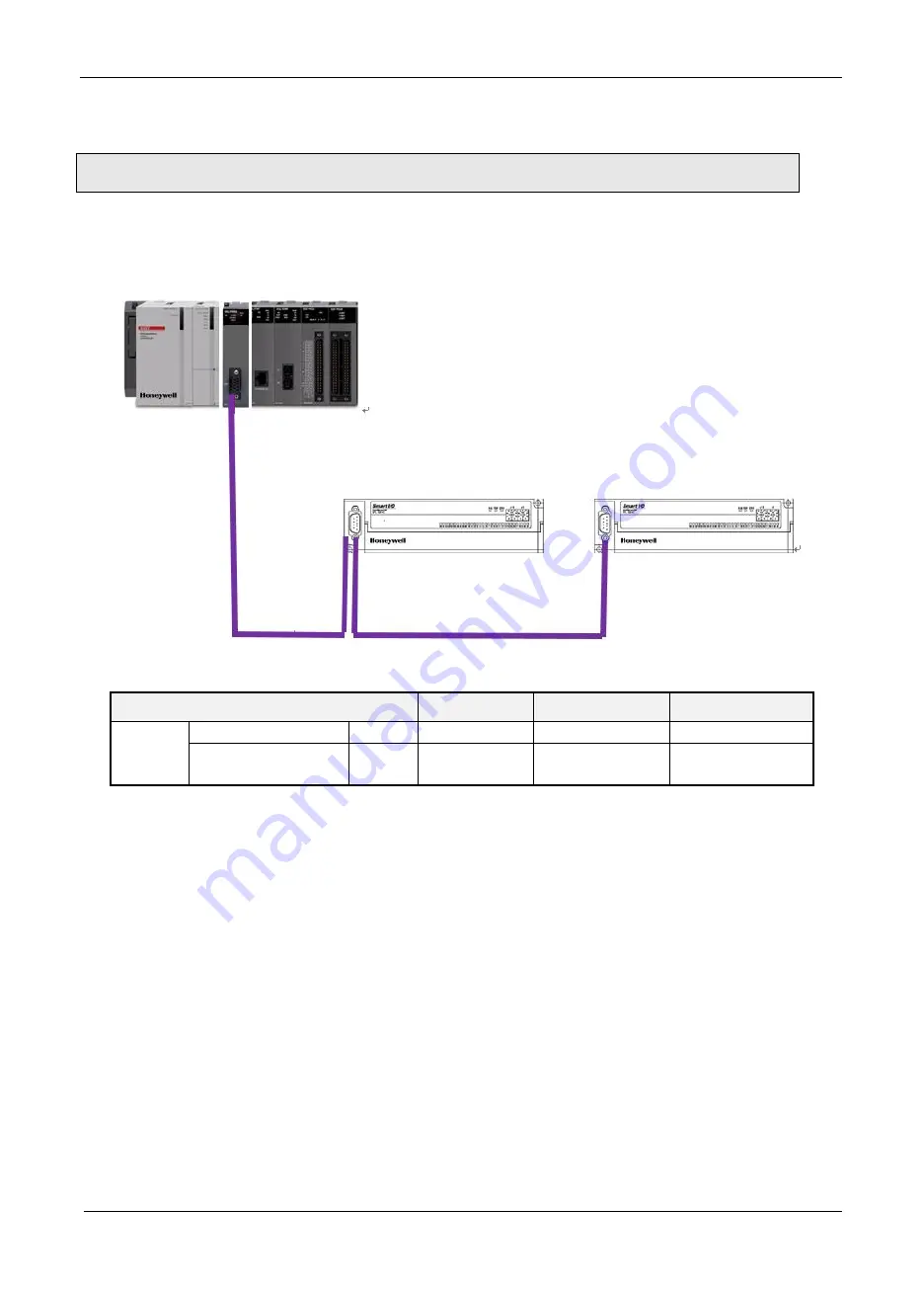
This example shows a program that is installed on No. 0 slot of ML200 No. 0 base, sending and
receiving data to Smart I/O module. (Station Number 4 and 2)
[Figure 10.3.1] I/O Structure and Sending/Receiving Data
Sending/Receiving Structure
Read Area
Save Area
Size (byte)
2MLL-
PMEB
(Master)
MPL-TR4C
Sending
%MW0(4byte)
-
4
MPL-D24C
Receiving
-
%MW200(4byte)
4
[Table 10.3.1] High-Speed Link Sending/Receiving Map
In the table above, ML200 CPU sends 4 byte data in %MW0 area to MPL-TR4C and saves 4 byte
(32 points) input data of MPL-D24C in %MW200 area of ML200 CPU
10.3.1 N Configurator settings
To exchange data between the systems as in [Table 10.3.1], it is convenient for the user to write
high-speed link sending/receiving map. In addition, it is necessary to write high-speed link
parameters after setting Network Configuration through N Configurator and download to PLC in
order to send/receive data as in [Table 10.3.1].


