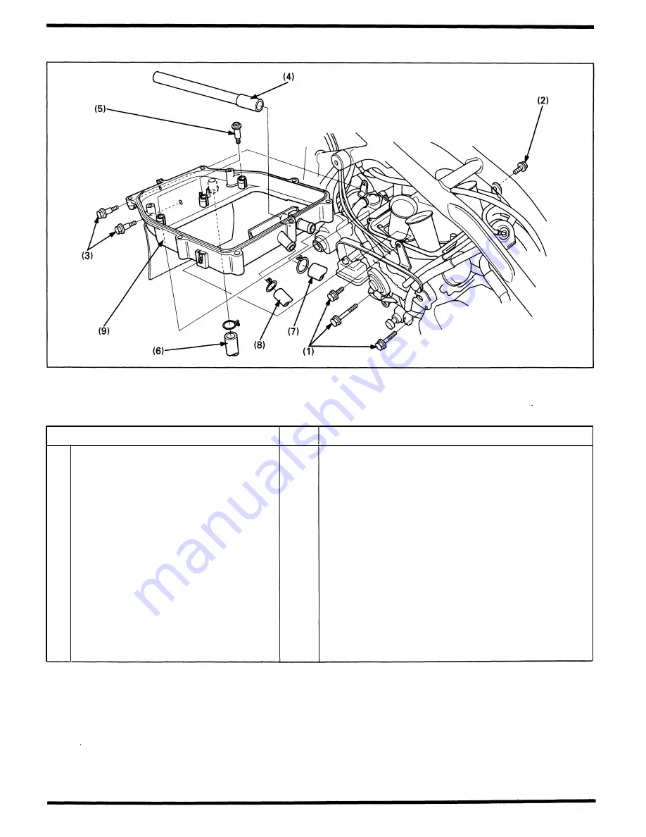
Fuel System
Air Cleaner Housing Removal/Installation
Requisite Service
•
Fuel tank remova l/instal lation (page 2-2)
Procedure
Removal Order
( 1 )
Left middle cover stay bolt
(2) Right m iddle cover stay bolt
(3)
Front pu lse secondary a i r i njection control
va lve bolt
(4)
Rea r pu lse secondary air i njection control
valve air i ntake pipe
(5) Air cleaner housing screw
(6) Front pu lse secondary air i njection control
valve a i r i ntake tu be
(7) Rear pu lse secondary air i njection control
valve air i ntake tu be
(8)
Crankcase breather tu be
(9)
Air cleaner housing
Q'ty
3
1
2
1
3
1
1
1
1
•
Air cleaner removal/instal lation (page 3-5)
Remarks
Installation is in the reverse order of removal.
Ca lifornia type only
Cal ifornia type only
California type only
Ca lifornia type only
Move the air cleaner housing out of the carbu retor on
the left.
CAUTION
•
Be careful not to damage the air cleaner housing dur-
ing removal/ installation.
5-3
Содержание Magna VF750C
Страница 1: ...1994 2003 MAGNA VF750C CD HONDA MOTOR CO LTD 1994 ...
Страница 2: ......
Страница 7: ...MEMO ...
Страница 47: ...MEMO ...
Страница 59: ...Lubrication System Lubrication System Diagram AFTER 94 9 OIL PRESSURE RELIEF VALVE 4 2 1 CAMSHAFT ...
Страница 65: ...Fuel System Carburetor Removal Installation 5 4 ...
Страница 67: ...Fuel System Carburetor Separation 1 5 26 5 6 ...
Страница 69: ...Fuel System Carburetor DisassemblyIAssembly 23 1 2 1 5 1 4 0 ring gasket 5 8 ...
Страница 71: ...Fuel System Carburetor Combination 27 D D No 1 CARBURETOR 25 0 RING COTIER PIN 5 5 1 0 ...
Страница 81: ...Cooling System System Flow Pattern 1 SIPHON TUBE 5 THERMOSTAT 2 RESERVE TANK 3 WATE PUMP 6 2 ...
Страница 87: ...MEMO ...
Страница 95: ...Cylinder Head Valves Cylinder Head Removal Installation 2 c 44 4 4 32 1 c 1 2 1 2 9 6 4 3 c 13 1 3 9 8 4 ...
Страница 109: ...MEMO ...
Страница 113: ...Clutch System Clutch Removal 9 4 3 1 3 1 2 1 0 l a TooL I page 9 9 8 7 ...
Страница 115: ...Clutch System Clutch Installation 1 0 0 9 6 ...
Страница 121: ...Gearshift Linkage Gearshift Linkage Removal Installation 8 SHIFTER PLATE ASSEMBLY 1 1 0 4 ...
Страница 123: ...MEMO ...
Страница 125: ...Crankshaft Piston Transmission Crankcase Separation 6 5 1 1 2 ...
Страница 131: ...Crankshaft Piston Transmission Transmission Removal Installation 1 1 1 8 ...
Страница 143: ...MEMO ...
Страница 145: ...Front Wheel Suspension Steering Handlebar Removal Installation 1 c2 3 2 3 1 7 1 1 0 1 5 1 2 2 ...
Страница 151: ...Front Wheel Suspension Steering Fork Disassembly 1 10 1 2lr Ja il l i 1 8 s 1 9 9 171 8 1 2 8 1 4 6 7 91 14 15 lB 1 6 ...
Страница 153: ...Front Wheel Suspension Steering Fork Assembly 3 4 s P e c 8 0 8 5 8 8 c 20 2 0 14 1 2 1 0 2 1 3 5 c 23 2 3 17 1 8 17 15 ...
Страница 159: ...Rear Wheel Suspension Rear Wheel Removal Installation 1 5 1 8 7 022 2 2 1 6 1 2 c93 9 3 63 2 9 1 0 1 3 2 ...
Страница 161: ...Rear Wheel Suspension Rear Wheel DisassemblyIAssembly 8 3 9 7 2 8 6 1 1 1 0 3 1 3 4 4 5 c1 08 1 0 8 79 4 ...
Страница 187: ...Charging System Alternator Alternator Removal Installation 5 4 6 1 5 1 0 7 012 1 2 9 1 c12 1 2 9 LIQUID SEALANT AREA ...
Страница 189: ...MEMO ...
Страница 209: ...Electric Starter Starter Clutch Starter Motor DisassemblyIAssembly 6 8 1 C5 0 5 3 6 9 1 6 2 3 4 5 ALIG N 1 7 8 ...
Страница 223: ...MEMO ...
Страница 227: ...MEMO ...
Страница 243: ...Appendix A Part Numbers 23 10 Carburetor Assembly ...
Страница 283: ...Appendix A Part Numbers 23 50 Speedometer Tachometer ...
Страница 297: ...MEMO ...
Страница 305: ... 1 ...


