General Information
Lubrication
&
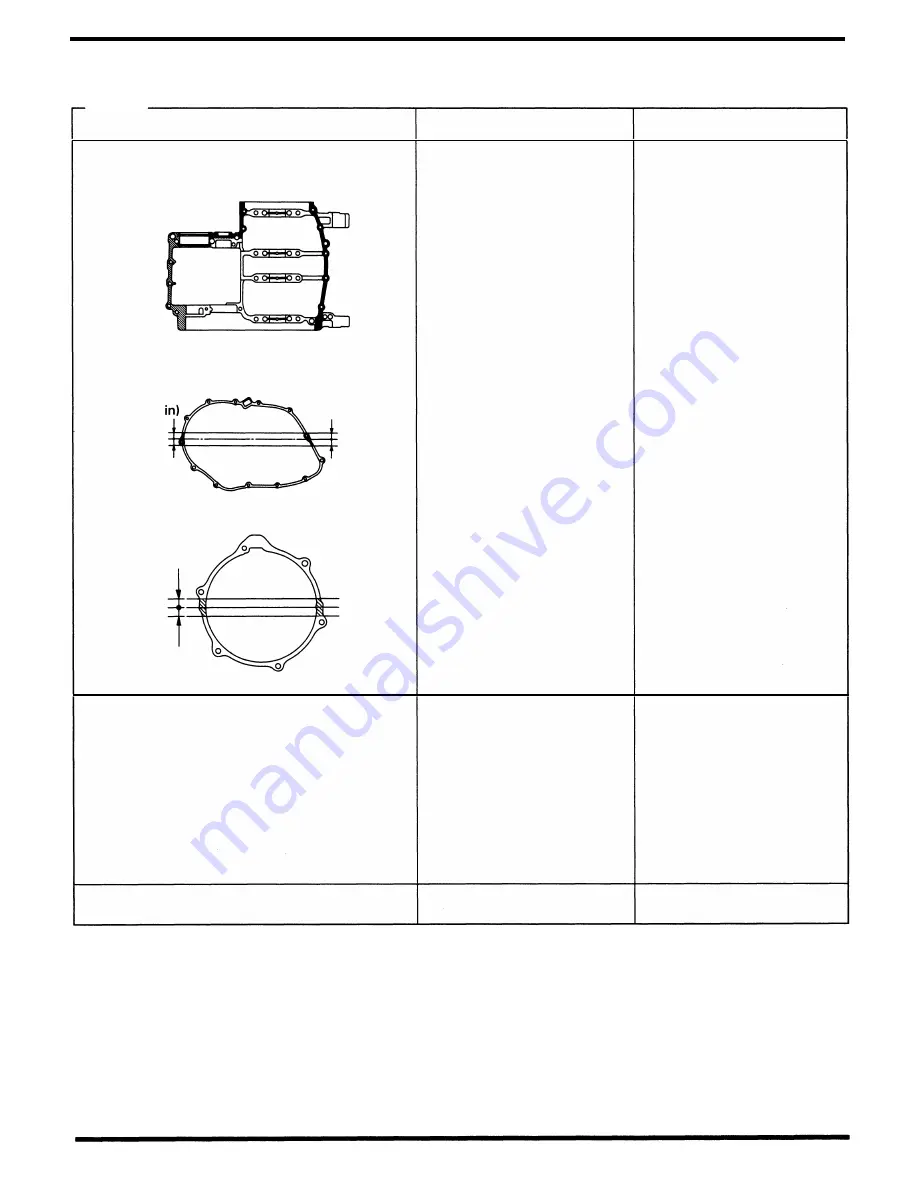
Seal Points
Engine
Location
Crankcase mating surface
Right crankcase cover mating surface
20-30 mm
(0.8-1.2
Left crankcase cover mating surface
20-30 mm
(0.8-1.2 in)
Cylinder head semi-circular cut-out
Crankshaft main bearing thrust surface
Connecting rod big end bearing
small end
Valve stem (valve guide sliding surface)
VaJve lifter outer sliding surface
Camshaft lobes/journals
M3/4, C5 and shifter gear (shift fork grooves)
Shift fork shaft sliding area
Shift drum
Primary drive gear sliding area
Each gear
Cylinder head cover gasket mating surface
(cover side)
Material
Liquid sealant
Molybdenum disulfide oil
(A mixture of 1/2 engine oil
and 1/2 molybdenum disulfide
grease)
Honda Bond A
Remarks
•
Wipe off the excess sealant
•
Do not apply the sealant to
near the bearing
1-17
Содержание Magna VF750C
Страница 1: ...1994 2003 MAGNA VF750C CD HONDA MOTOR CO LTD 1994 ...
Страница 2: ......
Страница 7: ...MEMO ...
Страница 47: ...MEMO ...
Страница 59: ...Lubrication System Lubrication System Diagram AFTER 94 9 OIL PRESSURE RELIEF VALVE 4 2 1 CAMSHAFT ...
Страница 65: ...Fuel System Carburetor Removal Installation 5 4 ...
Страница 67: ...Fuel System Carburetor Separation 1 5 26 5 6 ...
Страница 69: ...Fuel System Carburetor DisassemblyIAssembly 23 1 2 1 5 1 4 0 ring gasket 5 8 ...
Страница 71: ...Fuel System Carburetor Combination 27 D D No 1 CARBURETOR 25 0 RING COTIER PIN 5 5 1 0 ...
Страница 81: ...Cooling System System Flow Pattern 1 SIPHON TUBE 5 THERMOSTAT 2 RESERVE TANK 3 WATE PUMP 6 2 ...
Страница 87: ...MEMO ...
Страница 95: ...Cylinder Head Valves Cylinder Head Removal Installation 2 c 44 4 4 32 1 c 1 2 1 2 9 6 4 3 c 13 1 3 9 8 4 ...
Страница 109: ...MEMO ...
Страница 113: ...Clutch System Clutch Removal 9 4 3 1 3 1 2 1 0 l a TooL I page 9 9 8 7 ...
Страница 115: ...Clutch System Clutch Installation 1 0 0 9 6 ...
Страница 121: ...Gearshift Linkage Gearshift Linkage Removal Installation 8 SHIFTER PLATE ASSEMBLY 1 1 0 4 ...
Страница 123: ...MEMO ...
Страница 125: ...Crankshaft Piston Transmission Crankcase Separation 6 5 1 1 2 ...
Страница 131: ...Crankshaft Piston Transmission Transmission Removal Installation 1 1 1 8 ...
Страница 143: ...MEMO ...
Страница 145: ...Front Wheel Suspension Steering Handlebar Removal Installation 1 c2 3 2 3 1 7 1 1 0 1 5 1 2 2 ...
Страница 151: ...Front Wheel Suspension Steering Fork Disassembly 1 10 1 2lr Ja il l i 1 8 s 1 9 9 171 8 1 2 8 1 4 6 7 91 14 15 lB 1 6 ...
Страница 153: ...Front Wheel Suspension Steering Fork Assembly 3 4 s P e c 8 0 8 5 8 8 c 20 2 0 14 1 2 1 0 2 1 3 5 c 23 2 3 17 1 8 17 15 ...
Страница 159: ...Rear Wheel Suspension Rear Wheel Removal Installation 1 5 1 8 7 022 2 2 1 6 1 2 c93 9 3 63 2 9 1 0 1 3 2 ...
Страница 161: ...Rear Wheel Suspension Rear Wheel DisassemblyIAssembly 8 3 9 7 2 8 6 1 1 1 0 3 1 3 4 4 5 c1 08 1 0 8 79 4 ...
Страница 187: ...Charging System Alternator Alternator Removal Installation 5 4 6 1 5 1 0 7 012 1 2 9 1 c12 1 2 9 LIQUID SEALANT AREA ...
Страница 189: ...MEMO ...
Страница 209: ...Electric Starter Starter Clutch Starter Motor DisassemblyIAssembly 6 8 1 C5 0 5 3 6 9 1 6 2 3 4 5 ALIG N 1 7 8 ...
Страница 223: ...MEMO ...
Страница 227: ...MEMO ...
Страница 243: ...Appendix A Part Numbers 23 10 Carburetor Assembly ...
Страница 283: ...Appendix A Part Numbers 23 50 Speedometer Tachometer ...
Страница 297: ...MEMO ...
Страница 305: ... 1 ...


