How To Use This Manual
Finding The Information You Need
•
This manual is devided into sections which cover each of the
m ajor comonents of the motorcycle.
To quickly find the section you are interested in, the first page
of each sections is marked with a black tab that lines up with
one of the thumb index tabs before this page .
The first page of each section lists the table of contents wi
thin the section .
Read the service information and trobleshooting related to
the section before you begin working .
•
An index of the entire book is provided in the last chapter
to directly locate the information you need .
N ote On the Explanation Method Of This Manual
•
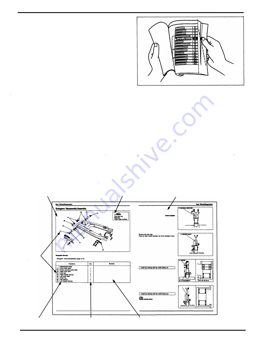
The removal and installation of parts are for the most part illustrated by large and clear illustrations that should provide
the reader with visual aid in understanding the major point for servicing .
•
The system illustrations are augmented by call outs whose numbers or letters indicate the order in which the parts should
be removed or installed .
•
The sequence of steps represented numerically a re differentiated from the ones represented alphabetically to notify
the reader that they must perform these steps separately.
•
The illustrations may contain symbols to indicate necessary service procedures and precautions that need to be taken .
Refer to the next page for the meaning of each symbo l .
•
Also in the illustration is a chart that lists information such as the order in which the parts is removal/installed, the name
of the part, and some extra notes that may needed .
•
Step by step instructions are provided to supplement the illustrations when datailed explanation of the procedu re is
necessary or illustrations alone would not suffice.
•
Service procedures required before or after the procedu re described on that particular page, or inspection/adjustment
procedures required following the installation of parts, are described under the title Requisite Service .
•
Standard workshop procedures and knowledge covered in the Common Service Manual are abbreviated in this manual .
System illustration
Step
sequence
(numerals
or alphabets)
Part name
12-14
Symbols
........., ....... _
....
,.._........
..........
....
g.,.
............. .,___,
,
............
....
. , ..
._._.....
....
13-111
Number of parts
Detailed description
of the procedure
............................
.......... _...._._, ... .........,....,..
I!SI
---
lllil
---
-
Cllwfully ............
.........
.................. ..
-
....
�
---··--
--
..,_
-
-
t.eflllly,.. ....
� .........................
-
....
-
111UNMGDIWD
Extra notes or precaution
related to the service procedure
u-
.. ...
._..
u-
.....
12-16
Содержание Magna VF750C
Страница 1: ...1994 2003 MAGNA VF750C CD HONDA MOTOR CO LTD 1994 ...
Страница 2: ......
Страница 7: ...MEMO ...
Страница 47: ...MEMO ...
Страница 59: ...Lubrication System Lubrication System Diagram AFTER 94 9 OIL PRESSURE RELIEF VALVE 4 2 1 CAMSHAFT ...
Страница 65: ...Fuel System Carburetor Removal Installation 5 4 ...
Страница 67: ...Fuel System Carburetor Separation 1 5 26 5 6 ...
Страница 69: ...Fuel System Carburetor DisassemblyIAssembly 23 1 2 1 5 1 4 0 ring gasket 5 8 ...
Страница 71: ...Fuel System Carburetor Combination 27 D D No 1 CARBURETOR 25 0 RING COTIER PIN 5 5 1 0 ...
Страница 81: ...Cooling System System Flow Pattern 1 SIPHON TUBE 5 THERMOSTAT 2 RESERVE TANK 3 WATE PUMP 6 2 ...
Страница 87: ...MEMO ...
Страница 95: ...Cylinder Head Valves Cylinder Head Removal Installation 2 c 44 4 4 32 1 c 1 2 1 2 9 6 4 3 c 13 1 3 9 8 4 ...
Страница 109: ...MEMO ...
Страница 113: ...Clutch System Clutch Removal 9 4 3 1 3 1 2 1 0 l a TooL I page 9 9 8 7 ...
Страница 115: ...Clutch System Clutch Installation 1 0 0 9 6 ...
Страница 121: ...Gearshift Linkage Gearshift Linkage Removal Installation 8 SHIFTER PLATE ASSEMBLY 1 1 0 4 ...
Страница 123: ...MEMO ...
Страница 125: ...Crankshaft Piston Transmission Crankcase Separation 6 5 1 1 2 ...
Страница 131: ...Crankshaft Piston Transmission Transmission Removal Installation 1 1 1 8 ...
Страница 143: ...MEMO ...
Страница 145: ...Front Wheel Suspension Steering Handlebar Removal Installation 1 c2 3 2 3 1 7 1 1 0 1 5 1 2 2 ...
Страница 151: ...Front Wheel Suspension Steering Fork Disassembly 1 10 1 2lr Ja il l i 1 8 s 1 9 9 171 8 1 2 8 1 4 6 7 91 14 15 lB 1 6 ...
Страница 153: ...Front Wheel Suspension Steering Fork Assembly 3 4 s P e c 8 0 8 5 8 8 c 20 2 0 14 1 2 1 0 2 1 3 5 c 23 2 3 17 1 8 17 15 ...
Страница 159: ...Rear Wheel Suspension Rear Wheel Removal Installation 1 5 1 8 7 022 2 2 1 6 1 2 c93 9 3 63 2 9 1 0 1 3 2 ...
Страница 161: ...Rear Wheel Suspension Rear Wheel DisassemblyIAssembly 8 3 9 7 2 8 6 1 1 1 0 3 1 3 4 4 5 c1 08 1 0 8 79 4 ...
Страница 187: ...Charging System Alternator Alternator Removal Installation 5 4 6 1 5 1 0 7 012 1 2 9 1 c12 1 2 9 LIQUID SEALANT AREA ...
Страница 189: ...MEMO ...
Страница 209: ...Electric Starter Starter Clutch Starter Motor DisassemblyIAssembly 6 8 1 C5 0 5 3 6 9 1 6 2 3 4 5 ALIG N 1 7 8 ...
Страница 223: ...MEMO ...
Страница 227: ...MEMO ...
Страница 243: ...Appendix A Part Numbers 23 10 Carburetor Assembly ...
Страница 283: ...Appendix A Part Numbers 23 50 Speedometer Tachometer ...
Страница 297: ...MEMO ...
Страница 305: ... 1 ...


