Crankshaft/Piston/Transmission
N OTE
•
Mark a l l pa rts d u ring disassembly so they can be replaced in their original locations.
•
All bea ring inserts are select fitted and are identified by color code. Select replacement bea ri ngs from the code
ta ble ( page
1 1 - 1 6).
After insta l ling new bea rings, recheck them with plastigauge to verify the clea rance.
•
Apply molybdenum disu lfide oil to the con necting rod/main journal bea rings, main journal and crankpi n.
Requisite Service
•
Refer to Service Information (page
1 1 - 1 )
Procedure
Removal Order
( 1 )
Connecti ng rod bea ri ng cap n ut
(2)
Connecting rod bea ring ca p
(3)
Connecting rod/piston assem bly
(4)
Connecti ng rod bearing
(5)
Crankshaft
(6)
Crankshaft main journal bearing
(7) Front cam chain tensioner sli pper bolt
(8)
Front cam chain tensioner sli pper
(9)
Rea r cam chain tensioner slipper bolt
( 1 0)
Rea r cam chain tensioner slipper
( 1 1 )
Front/rear cam chain slipper bolt
(
1 2
) F ront/rear cam chain sli pper
Installation Order
(
1 2
) Front/rear cam chai n sli pper
( 1 1 )
F ront/rear cam chain sli pper bolt
( 1 0)
Rea r ca m chain tensioner sli pper
(9)
Rea r cam cha in tensioner slipper bolt
(8)
Front cam chain tensioner slipper
(7) Front cam chain tensioner slipper bolt
(6)
Crankshaft main journal bearing
(5)
Crankshaft
(4)
Connecting rod bearing
(3)
Con necting rod/piston assembly
(2)
Connecting rod bea ring cap
( 1 )
Con necting rod bearing cap nut
Q'ty
Remarks
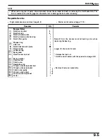
Insta l lation is in the reverse order of remova l .
8
4
NOTE
•
Note the direction of the bea ring ca p.
4
CAUTION
•
Do not try to remove the connecting rod/piston as-
sembly from the bottom of the cylinder. The oil ring
will become wedged in the gap between the cylinder
liner and the upper crankcase.
8
Wi pe a l l oil from bea ring seating a reas.
1
8
Wi pe a l l oil from bearing seating areas.
1
1
1
1
2
1
1
2
Clean and apply a locki ng agent to the th reads.
1
1
Clea n and apply a locking agent to the threads.
1
1
Clean a nd apply a locking agent to the th reads.
8
NOTE
•
At installation, align the oil holes between the crank-
case a n d bea r i n g , a n d t h e bea r i n g ta bs with t h e
groove i n the crankcase.
1
8
NOTE
•
At insta l l ation, a l i g n the o i l h oles between the con-
necting rod and bearing, and the beari ng tabs with the
groove in the connecti ng rod and bearing cap.
4
NOTE
•
Each connecti ng rod has an identification m ark; " M L7-
F" (Front), " M L7-R" (Rear).
•
At i n sta l l ati o n , i n sta l l the c o n n ecti n g rod/ p i st o n
assembly with the o i l h o l e on the connecting rod fac-
ing opposite the rotati ng di rection of the crankshaft.
4
8
NOTE
•
At i n sta l lati on, apply engine o i l to the th reads a n d
seati ng su rface of the nut.
•
Tighten the nuts gradually and a lternately.
1 1 -5
Содержание Magna VF750C
Страница 1: ...1994 2003 MAGNA VF750C CD HONDA MOTOR CO LTD 1994 ...
Страница 2: ......
Страница 7: ...MEMO ...
Страница 47: ...MEMO ...
Страница 59: ...Lubrication System Lubrication System Diagram AFTER 94 9 OIL PRESSURE RELIEF VALVE 4 2 1 CAMSHAFT ...
Страница 65: ...Fuel System Carburetor Removal Installation 5 4 ...
Страница 67: ...Fuel System Carburetor Separation 1 5 26 5 6 ...
Страница 69: ...Fuel System Carburetor DisassemblyIAssembly 23 1 2 1 5 1 4 0 ring gasket 5 8 ...
Страница 71: ...Fuel System Carburetor Combination 27 D D No 1 CARBURETOR 25 0 RING COTIER PIN 5 5 1 0 ...
Страница 81: ...Cooling System System Flow Pattern 1 SIPHON TUBE 5 THERMOSTAT 2 RESERVE TANK 3 WATE PUMP 6 2 ...
Страница 87: ...MEMO ...
Страница 95: ...Cylinder Head Valves Cylinder Head Removal Installation 2 c 44 4 4 32 1 c 1 2 1 2 9 6 4 3 c 13 1 3 9 8 4 ...
Страница 109: ...MEMO ...
Страница 113: ...Clutch System Clutch Removal 9 4 3 1 3 1 2 1 0 l a TooL I page 9 9 8 7 ...
Страница 115: ...Clutch System Clutch Installation 1 0 0 9 6 ...
Страница 121: ...Gearshift Linkage Gearshift Linkage Removal Installation 8 SHIFTER PLATE ASSEMBLY 1 1 0 4 ...
Страница 123: ...MEMO ...
Страница 125: ...Crankshaft Piston Transmission Crankcase Separation 6 5 1 1 2 ...
Страница 131: ...Crankshaft Piston Transmission Transmission Removal Installation 1 1 1 8 ...
Страница 143: ...MEMO ...
Страница 145: ...Front Wheel Suspension Steering Handlebar Removal Installation 1 c2 3 2 3 1 7 1 1 0 1 5 1 2 2 ...
Страница 151: ...Front Wheel Suspension Steering Fork Disassembly 1 10 1 2lr Ja il l i 1 8 s 1 9 9 171 8 1 2 8 1 4 6 7 91 14 15 lB 1 6 ...
Страница 153: ...Front Wheel Suspension Steering Fork Assembly 3 4 s P e c 8 0 8 5 8 8 c 20 2 0 14 1 2 1 0 2 1 3 5 c 23 2 3 17 1 8 17 15 ...
Страница 159: ...Rear Wheel Suspension Rear Wheel Removal Installation 1 5 1 8 7 022 2 2 1 6 1 2 c93 9 3 63 2 9 1 0 1 3 2 ...
Страница 161: ...Rear Wheel Suspension Rear Wheel DisassemblyIAssembly 8 3 9 7 2 8 6 1 1 1 0 3 1 3 4 4 5 c1 08 1 0 8 79 4 ...
Страница 187: ...Charging System Alternator Alternator Removal Installation 5 4 6 1 5 1 0 7 012 1 2 9 1 c12 1 2 9 LIQUID SEALANT AREA ...
Страница 189: ...MEMO ...
Страница 209: ...Electric Starter Starter Clutch Starter Motor DisassemblyIAssembly 6 8 1 C5 0 5 3 6 9 1 6 2 3 4 5 ALIG N 1 7 8 ...
Страница 223: ...MEMO ...
Страница 227: ...MEMO ...
Страница 243: ...Appendix A Part Numbers 23 10 Carburetor Assembly ...
Страница 283: ...Appendix A Part Numbers 23 50 Speedometer Tachometer ...
Страница 297: ...MEMO ...
Страница 305: ... 1 ...

