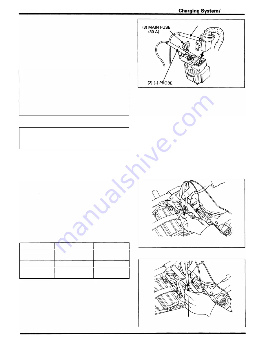
Disconnect the sta rter relay switch connector and remove
the main fuse (30 A).
Reconnect the connector onto the relay switch.
Connect the a m m eter between the fuse holder term inals
as shown.
Start the engine and i ncrease the engine speed g radually
and check that the voltage and a m pere are reg ulated .
CAUTION
•
Be careful not to short any tester probes.
•
Although the current could be measured when the
ammeter is connected between the battery positive
terminal and the positive cable, a sudden surge of
currant to the starter motor could damage the
ammeter.
•
Always turn the ignition switch OFF when conduct
ing the test. Disconnecting the ammeter or wire
when currant is flowing may damage the ammeter.
NOTE
•
Before making this test, a l l the lights and the other
electrical eq u ipment should b� OFF.
•
Use fu l ly charged battery to make this test i n order
to get a correct measurement.
Regulated:
Battery terminals:
Charging current:
14 - 1 5.5 V/3,000 rpm
0 - 0.5 A/3,000 rpm
Regulator /Rectifier
System Inspection
Remove the seat ( page 2-2) .
Disconnect t h e reg u lator/rectifier connectors.
Check the connectors for loose or corroded term inal.
Measu re the following between con nector terminal of the
wi re harness side.
Item
Terminals
Specification
Battery charging Red/Wh ite (+)
Battery voltage
l i n e
and G reen (-)
should reg ister.
G round line
G reen and ground Contin uity exist.
·
Charging coi l
Yellow and Yellow 0. 1 - 1 .0
(}
line
(20°C/68°F)
If the c h a rg i n g coi l l i n e rea d i ng is out of s pecificatio n ,
check t h e a lternator ( page 1 5-9).
Alternator
( 1 ) (+) PROBE: R E D/WHITE
( 1 ) REG U LATOR/RECTIFIER 4P CON N ECTOR
(WI RE HARN ESS SIDE)
( 1 ) REG U LATOR/RECTIFIER 3P CON NECTOR
(WIRE HARN ESS SIDE)
1 5-7
Содержание Magna VF750C
Страница 1: ...1994 2003 MAGNA VF750C CD HONDA MOTOR CO LTD 1994 ...
Страница 2: ......
Страница 7: ...MEMO ...
Страница 47: ...MEMO ...
Страница 59: ...Lubrication System Lubrication System Diagram AFTER 94 9 OIL PRESSURE RELIEF VALVE 4 2 1 CAMSHAFT ...
Страница 65: ...Fuel System Carburetor Removal Installation 5 4 ...
Страница 67: ...Fuel System Carburetor Separation 1 5 26 5 6 ...
Страница 69: ...Fuel System Carburetor DisassemblyIAssembly 23 1 2 1 5 1 4 0 ring gasket 5 8 ...
Страница 71: ...Fuel System Carburetor Combination 27 D D No 1 CARBURETOR 25 0 RING COTIER PIN 5 5 1 0 ...
Страница 81: ...Cooling System System Flow Pattern 1 SIPHON TUBE 5 THERMOSTAT 2 RESERVE TANK 3 WATE PUMP 6 2 ...
Страница 87: ...MEMO ...
Страница 95: ...Cylinder Head Valves Cylinder Head Removal Installation 2 c 44 4 4 32 1 c 1 2 1 2 9 6 4 3 c 13 1 3 9 8 4 ...
Страница 109: ...MEMO ...
Страница 113: ...Clutch System Clutch Removal 9 4 3 1 3 1 2 1 0 l a TooL I page 9 9 8 7 ...
Страница 115: ...Clutch System Clutch Installation 1 0 0 9 6 ...
Страница 121: ...Gearshift Linkage Gearshift Linkage Removal Installation 8 SHIFTER PLATE ASSEMBLY 1 1 0 4 ...
Страница 123: ...MEMO ...
Страница 125: ...Crankshaft Piston Transmission Crankcase Separation 6 5 1 1 2 ...
Страница 131: ...Crankshaft Piston Transmission Transmission Removal Installation 1 1 1 8 ...
Страница 143: ...MEMO ...
Страница 145: ...Front Wheel Suspension Steering Handlebar Removal Installation 1 c2 3 2 3 1 7 1 1 0 1 5 1 2 2 ...
Страница 151: ...Front Wheel Suspension Steering Fork Disassembly 1 10 1 2lr Ja il l i 1 8 s 1 9 9 171 8 1 2 8 1 4 6 7 91 14 15 lB 1 6 ...
Страница 153: ...Front Wheel Suspension Steering Fork Assembly 3 4 s P e c 8 0 8 5 8 8 c 20 2 0 14 1 2 1 0 2 1 3 5 c 23 2 3 17 1 8 17 15 ...
Страница 159: ...Rear Wheel Suspension Rear Wheel Removal Installation 1 5 1 8 7 022 2 2 1 6 1 2 c93 9 3 63 2 9 1 0 1 3 2 ...
Страница 161: ...Rear Wheel Suspension Rear Wheel DisassemblyIAssembly 8 3 9 7 2 8 6 1 1 1 0 3 1 3 4 4 5 c1 08 1 0 8 79 4 ...
Страница 187: ...Charging System Alternator Alternator Removal Installation 5 4 6 1 5 1 0 7 012 1 2 9 1 c12 1 2 9 LIQUID SEALANT AREA ...
Страница 189: ...MEMO ...
Страница 209: ...Electric Starter Starter Clutch Starter Motor DisassemblyIAssembly 6 8 1 C5 0 5 3 6 9 1 6 2 3 4 5 ALIG N 1 7 8 ...
Страница 223: ...MEMO ...
Страница 227: ...MEMO ...
Страница 243: ...Appendix A Part Numbers 23 10 Carburetor Assembly ...
Страница 283: ...Appendix A Part Numbers 23 50 Speedometer Tachometer ...
Страница 297: ...MEMO ...
Страница 305: ... 1 ...


