


Rev. 1.00
294 of 576
January 28, 2022
32-Bit Arm
®
Cortex
®
-M0+ MCU
HT32F54231/HT32F54241/HT32F54243/HT32F54253
15 Motor Control T
imer (MCTM)
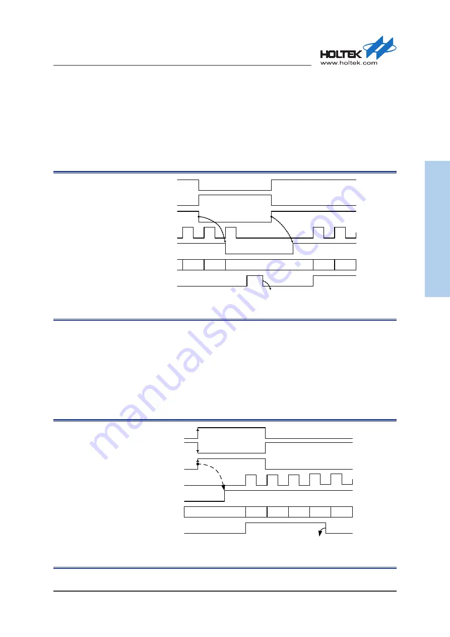
Pause Mode
In the Pause Mode, the selected STI input signal level is used to control the counter start/stop
operation. The counter starts to count when the selected STI signal is at a high level and stops
counting when the STI signal is changed to a low level. When the counter stops, it will maintain
its present value and not be reset. Since the Pause function depends upon the STI level to control
the counter stop/start operation, the selected STI trigger signal cannot be derived from the TI0BED
signal.
CK_ CNT
STI
CNT_ EN
27
CNTR
28
29
30
31
TEVIF
Sync.
Software clearing
STI source signal
(polarity=0)
STI source signal
Sync.
(polarity=1)
Figure 82. MCTM in Pause Mode
Trigger Mode
After the counter is disabled to count, the counter can resume counting when an STI rising edge
signal occurs. When an STI rising edge occurs, the counter will start to count from the current
value in the counter. Note that if the STI signal is selected to be sourced from the UEV1G bit
software trigger, the counter will not resume counting. When software triggering using the UEV1G
bit is selected as the STI source signal, there will be no clock pulse generated which can be used to
make the counter resume counting. Note that the STI signal is only used to enable the counter to
resume counting and has no effect to stop counting.
CK_CNT
STI
CNT_EN
27
CNTR
(Up-counting)
29
30
31
32
TEVIF
Sync.
Software clearing
28
STI source signal
(polarity=0)
STI source signal
(polarity=1)
Figure 83. MCTM in Trigger Mode