157
Step 8
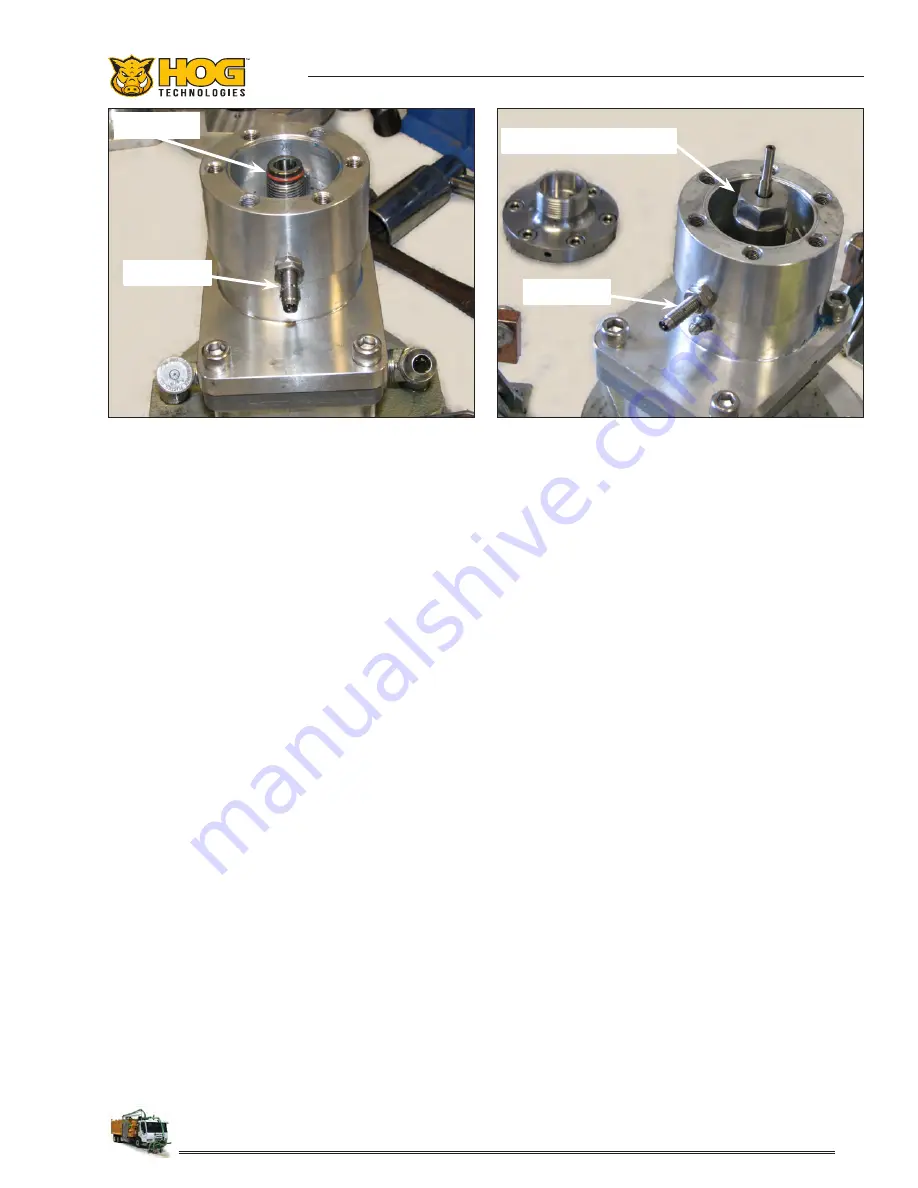
Install The Swivel Tit Assembly/Gland Nut.
Inspect the O-ring seal near the top of the thru-shaft and make sure it is not damaged. Replace the
O-ring if it shows any sign of nicks, cuts, deterioration or wear. Then apply a light layer of grease to
the O-Ring. The grease will help the swivel tit assembly slide over the O-ring and reduce the pos-
sibility for the O-ring to be pushed out of the seat or damaged as the swivel tit assembly is installed.
Figure 13.
Apply anti-seize to the thru-shaft threads. The anti-seize is extremely important and will prevent the
stainless steel threads on the shaft and swivel tit assembly from galling and seizing.
If anti-seize
is not used and the threads seize, the thru-shaft and the swivel tit assembly will be ruined
and the thru-shaft motor will have to be completely disassembled and rebuilt!!
While holding the thru-shaft with the 3/4” (19mm) open end wrench, install the swivel tit assembly/
gland nut and hand tighten. Then use a 15/16” (24mm) deep well socket and a torque wrench to
tighten swivel tit assembly/gland nut to 50 ft lbs. Figure 14.
Step 7
Set The Rpm Sensor To Counter Washer Gap
Set the gap between the rpm sensor and the counter washer tabs. Use a feeler gauge of .015 (fifteen
thousandths) to set the gap. Turn the Thru-Shaft until one tab lines up with the Sensor. Make sure
that you do not scrape the rubber end with the tab as it will ruin the sensor. Figures 13 & 14.
If the gap is more than .015” use a flat screw driver and hammer to lightly tap the tab closer to the
sensor.
If the gap is tighter than .015” use a flat screwdriver to pry the tab away from the sensor.
Turn the Thru-Shaft until the other tab lines up with the sensor and repeat the process. It is impor-
tant that you keep the gap within two thousandths either way. If there is more than .05 thousandths
variance from one tab to the other it can confuse the PLC system and stop head rotation.
Swivel Tit Assembly/Gland Nut
RPM Sensor
O-ring Seal
RPM Sensor
Figure 13: O-ring seal seat at the top of the thru-shaft
greased and the threads below the seal coated
with anti-seize.
Figure 14: Swivel tit assembly/gland nut installed on the
thru-shaft and torqued to 50 Ft lbs.
Содержание Stripe Hog SH8000
Страница 1: ...Operations Manual...
Страница 2: ...2...
Страница 6: ...6 NOTES...
Страница 16: ...16 NOTES...
Страница 80: ...80 NOTES...
Страница 166: ...166 NOTES...
Страница 171: ...171 Troubleshooting UHP POWER FRAME...
Страница 172: ...172 Troubleshooting...
Страница 173: ...173 Appendix 2 Tools Spare Parts...
Страница 174: ...174 Tools Spare Parts...
Страница 175: ...175 Appendix 3 Daily Report Pre Op Checklist 1 877 HOG ROAD WWW STRIPEHOGSUPPORT COM...
Страница 176: ...176 Daily Report Pre Op Checklist 1 877 HOG ROAD WWW STRIPEHOGSUPPORT COM 61...
Страница 178: ...178 Spray Bar Nozzle Configuration 1 877 HOG ROAD WWW STRIPEHOGSUPPORT COM 63 Spray Bar Configuration Charts...
Страница 179: ...179 Spray Bar Nozzle Configuration 1 877 HOG ROAD WWW STRIPEHOGSUPPORT COM 64...
Страница 180: ...180 Spray Bar Nozzle Configuration 1 877 HOG ROAD WWW STRIPEHOGSUPPORT COM 65...
Страница 181: ...181 Spray Bar Nozzle Configuration 1 877 HOG ROAD WWW STRIPEHOGSUPPORT COM 66...
Страница 183: ...183 Spray Bar Nozzle Configuration 1 877 HOG ROAD WWW STRIPEHOGSUPPORT COM 68 Nozzle Calculation Sheet...
Страница 184: ...184 NOTES...
Страница 191: ......


