Electrical wiring
Service Manual
64
Accessories electrical installation
SMGB0066 rev.0 - 12/2009
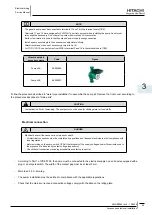
-To earth: connection (6), U shaped terminal.
-To the potentiostat: connections at (9) and (10), pins (7) and (8) respectively.
note
Use original wires only. To avoid any risk of corrosion due to reverse polarity do not lengthen nor shorten the
-
wires.
Use a socket base near to the storage heater for this purpose.The protective anode starts comes into operation
-
when the storage heater is full of water. When there is no water the control pilot light (11) lights up red and
blinks on and off.
lf the pilot light (11) is green, this shows that the storage heater is receiving a protective current. lf the pilot
-
light is not on or lights up red and blinks, check the connections, contacts and mains supply. lf this anomaly
continues, contact the fitter or our Customer Technical Service Department.
In the case of vertically installed storage heaters from which water is not going to be extracted for periods of
-
more than 3 months, we recommend fitting an automatic purger at the D.H.W. outlet.
lf the storage heater is installed horizontally, we recommend the extraction of water at least once every 3
-
months.
The potentiostat (3) and connecting wires (4) must not be disconnected, except when the storage heater is
-
emptied.
Do not disconnect the protection system during periods of absense (holidays, etc.).
-
Occasionally check that the pilot light is working correctly (11).
-
Electric heater
¡
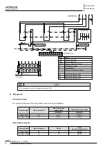
The electric heater is made of Incoloy alloy 825 and complies with the European Low Voltage Directive 2006/95/EC.
It comprises a flange that holds three U-Shaped heating elements for 2.5kw power resistances.
replace electric heater
•
The steps to be followed are:
Totally disconnect the unit from the main power supply.
1.
With the help of a tool remove the heater to be replaced. Be careful not to damage the enamel surface in case of
2.
enamelled tanks.
Insert the new heater in the same position as the old one.
3.
Connect again and plug into the main power supply.
4.
Safety measures
•
Before any intervention, totally disconnect the DHWT from the main power supply. All the connections circuits must be
disconnected.
Installation, configuration, start up and maintenance of heating elements must be carried out by an authorised electrical
fitter. All standards and regulations must be observed.
The user is responsible of ensuring that the essential requirements of the European Low Voltage Directive are respected.
Electric heating elements generates high temperatures. Precautions should be taken to protect goods and persons from
accidental burns during the operation and after the equipment has been disconnected or installed.
Note minimum cable section: Resistances of 2.5kw recommended cable: H05SJ-K accordance with UNE 21027, and will
have at least 2.5mm² section.
Содержание RHUE-3AVHN
Страница 1: ...Air to water Heat pump RHUE 3AVHN RHUE 4AVHN RHUE 5A V HN RHUE 6A V HN YUTAKI SERIES RHUE A V HN ...
Страница 2: ......
Страница 4: ......
Страница 6: ......
Страница 16: ......
Страница 34: ......
Страница 70: ......
Страница 166: ......
Страница 236: ...Spare parts Service Manual 234 Spare parts of Yutaki SMGB0066 rev 0 12 2009 8 2 2 DHWT Domestic Hot Water Tank ...
Страница 238: ......
Страница 260: ......
Страница 261: ......
Страница 262: ...SMGB0066 rev 0 12 2009 Printed in Spain ...


