


67
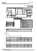
Electrical wiring diagram for RHUE-(5/6)AHN
SMGB0066 rev.0 - 12/2009
Electrical wiring
Service Manual
3
CN14
CN15
CN8
2
1
4
3
(B)
(A)
MF1
MF2
NF1
52C
EP
CN201
5
1
1
PCN203
3
2
4
3
E3
5
2
3
1
4
5
3
1
3
2
2
4
4
1
5
CN202
4
PWB
5
1
3
4
1
2
CN201
PCN203
3
3
203
PCN
3
5
5
1
PCN201
4
CN202
2
1
1
CB2
PCN201
5
2
(+)
CB1
(-)
W
V
R1
R2
(+)
(-)
C3
U
NF
3
PWB
MC
N
P
3
C
3
CN206
E2
1
C
W
U
1
V
NF
ISPM
R
L3
L1
E
6
C2
T
(B)
DCL
5
NF
(A)
1
N
C1
N'
(B)
(A)
L2
L3'
L2'
CE17
CE16
E'
E1
L1'
3
S
4
2
RB
TB3(PD)
RS
CE18
P1
TB1
L1
L2
N
L3
(A)
(B)
PWB5
47C
PF
PF
(B)
2
T
(A)
1
S
R
NF3
MP
N
am
e
o
f P
ar
ts
C
o
ntac
tor (f
or
Pu
mp)
M
o
tor (f
or
Pu
mp)
M
ar
k
52P
Thermistor (f
or Ambient T
emperature)
C
o
nnec
tor
(T
erminating C
onnec
tor)
Resistance (f
or 4-20mADC Signal)
Lo
w
Pr
es
su
re
S
en
so
r
Fr
oz
en
Pr
evention Heater for Pipin
g
C
o
nnec
tor
(T
erminating C
onnec
tor)
Thermistor (f
or Suc
tion Gas T
emperature)
High
Pr
essure Sensor
Thermistor (f
o
r E
va
p
o
ra
ti
n
g
G
as
T
em
p
er
at
u
re
)
C
o
nnec
tor (Rela
y C
onnec
tor)
Thermistor (f
or Liquid Refrigerant
Te
mperature)
Thermistor (f
or Inlet
W
ater
Te
m
p
er
at
u
re
)
Thermistor (f
or Discharge Gas
Te
mperature)
Pu
sh Button Switch (f
o
r S
to
p
p
ag
e)
So
le
n
o
id
V
alv
e (f
or Hot Gas By-pass)
Changeover Switch
El
ec
trical Expansion
Va
lv
e
Pu
sh Button Switch (f
or Star
ting)
So
le
n
o
id
V
alv
e (f
or Liquid Injec
tion)
Thermistor (f
or Outlet
W
at
er
T
em
p
er
at
u
re
)
M
ag
n
et
ic
4
-W
ay
V
alv
e
M
ar
k
R
ev
erse
Pr
otec
ti
o
n
R
el
ay
Resistance (f
or Star
ting)
C
ap
ac
it
o
r
C
ap
ac
it
o
r
Pr
inted Wiring Board (f
o
r
Re
verse
Pr
otec
tion)
Pr
inted Wiring Board (f
or
Fa
n
Po
wer Supply
)
M
ar
k
M
o
tor (f
or
C
o
mpressor)
Pr
inted Wiring Board (f
or I/O
)
O
il
H
ea
te
r
In
ve
rt
er
M
o
d
u
le
Re
ac
to
r
C
o
ntac
tor (f
or
C
o
mpressor)
M
o
tor (f
or F
an)
High
Pr
essure Switch
Po
wer
Fu
se f
or
C
o
mpressor
Noise
Fi
lter
Te
rminal Board (f
or
C
o
n
tr
o
l C
ir
cu
it
(1
) t
o
(2
0)
)
N
am
e
o
f P
ar
ts
Pr
inted Wiring Board (f
or Main
C
o
n
tr
o
l)
Noise
Fi
lter
Noise
Fi
lter
Tr
ansf
omer
Fu
se f
or
C
o
n
tr
o
l C
ir
cu
it
DC
R
21~30
CE
WH
20I
R1
EF
47C
1,2
R
C1
1,2
CB
PWB5
PWB3,4
PWB1
1,2,3,4
OH
1~18
ISPM
DCL
C1
NF
MV
,MV
C
21
1,2,C2,C3
NF
2,
MF1
DS
1~10
CS
ON
BS
OFF
BS
1~2
Tr
a
THM
ec
s
THM
THM
d
eh
THM
THM
1~5
NK
52C
1.2
PF
20G
PS (L)
PS (H)
THM
THM
PWB2
W
o
W
i
2
1
63H
TB
TB
CE
MC
N
am
e
o
f P
ar
ts
Te
rminal Board (f
or
Po
wer Supply
. H-Link)
RL,
OL
OFF
BS
E
ON
BS
EF
P
X
P
Pilot Lamp
Po
wer F
use
fo
r P
u
mp
Pu
sh Button Switch (f
o
r S
to
p
p
ag
e)
Pu
sh Button Switch (f
o
r S
ta
rting)
A
u
xiliar
y Rela
y
Ea
rt
h
Line
Co
nnec
tion
Line C
onnec
tion
Line C
onnec
tion
Line C
onnec
tion
Line C
onnec
tion
Line
Co
nnec
tion
Line C
onnec
tion
Line C
onnec
tion
Line C
onnec
tion
8
7
1
N
3
8
7
MP
P
EF
4
52P
2
P
X
L
DC
R
20
19
DS9
DS1
0
WH
DS1
DS5
DS2
DS3
DS4
OH
1
DS8
OH
2
O
H4
OH
3
DS6
DS7
12
14
3
P
X
5
52P
14
13
15
16
17
18
(Red
)
for Remote Indication
Power Supply
REM
OT
E
LO
CA
L
(W
hite)
(Red
)
(Red
)
(Red
)
(Black)
(W
hite)
(W
hite)
(W
hite)
(Red
)
(W
hite)
CE1
5
CE13
13
A2
A1
CE1
5
6
BS
2
OFF
7
CS
OFF
4
2
9
11
BSR
3
1
BSR
BS
ON
ON
47C
MV
M
M
MV
C
CN7
B
3
5
6
1
4
2
1
2
6
3
4
CN7
A
5
11
CE1
1
2
5
PCN6
3
5
1
3
1
5
PCN5
3
3
1
PCN
9
1
1
PCN7
PCN
8
3
CE28
CE27
NK
4
21
CE1
1
CE12
9
8
240V
220V
Tr
2
240V
NK
5
CE30
CE29
CE9
CE10
CE8
CE7
CE6
CE5
CE2
6
CE25
NK
3
20I
CS
52
52
CS
Y
Y
3
2
1
CN13
CE14
RL
1
4
CE24
CE23
CE2
2
CE2
1
2
CN12
1
4
4
3
3
3
3
52C
52P
~
OL
PWB2
PWB1
CN11
1
2
1
CN8
2
2
2
1
1
1
2
CN7
CN6
CN5
4
Y
3
Y
2
Y
1
Y
2
1
2
1
CN2
CN4
2
2
1
1
CN2
CN3
NK
2
20
G
CE4
CE3
7
Ea
rt
h
PCN3B
1
3
5
CN10B
CN10A
PCN3A
1
6
1
Tr
1
Ea
rt
h
PCN12
1
2
3
CN1
6
PR
Y
PR
Y
1
PCN
1
6
3
1
CN5
CN6
C
52
C
52
Y
E1
E1
Y
Y
A
Y
L
Y
20
E
Y
2
A
Y
E2
Y
L
20
Y
A
20
Y
A
20
B
20
B
5
PCN10
PCN4
3
1
PCN6
3
1
PCN5
63H
5
5
1
3
1
PCN2
3
1
3
20
Y
Y
Y
Y
220V
5
3
PCN9
3
5
2
1
2
1
3
PCN7
1
3
1
PCN8
3
5
R1
EF
CE2
A2
A1
NK
1
5
3
1
PC3
PC4
10
THM
eh
B
A
4
3
2
CN16
1
THM
1
ec
3
4
CN14
2
2
CN13
1
Wo
THM
CN12
1
2
3
4
THMs
4
3
d
THM
2
CN15
1
3
2
CN11
1
CN10
2
1
THMa
CN
9
2
THM
1
Wi
4
Y
3
Y
2
Y
1
Y
CN1
PCN4
PCN3
PCN2
1
3
3
1
1
3
CN9
PS(L)
PS(H)
2
1
CN3
3
2
1
3
CN4
1
3
PCN1
9
NF2
1
1
9
3.6.2.
Electrical wiring diagram for
r
HUE-(5/6)AH
n
Содержание RHUE-3AVHN
Страница 1: ...Air to water Heat pump RHUE 3AVHN RHUE 4AVHN RHUE 5A V HN RHUE 6A V HN YUTAKI SERIES RHUE A V HN ...
Страница 2: ......
Страница 4: ......
Страница 6: ......
Страница 16: ......
Страница 34: ......
Страница 70: ......
Страница 166: ......
Страница 236: ...Spare parts Service Manual 234 Spare parts of Yutaki SMGB0066 rev 0 12 2009 8 2 2 DHWT Domestic Hot Water Tank ...
Страница 238: ......
Страница 260: ......
Страница 261: ......
Страница 262: ...SMGB0066 rev 0 12 2009 Printed in Spain ...


