133
System MMI Pack (Room unit and RF receiver)
SMGB0066 rev.0 - 12/2009
Controller pack
Service Manual
4
4.22.2.3. locating the room Unit
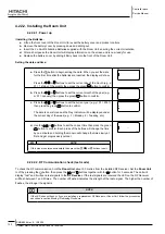
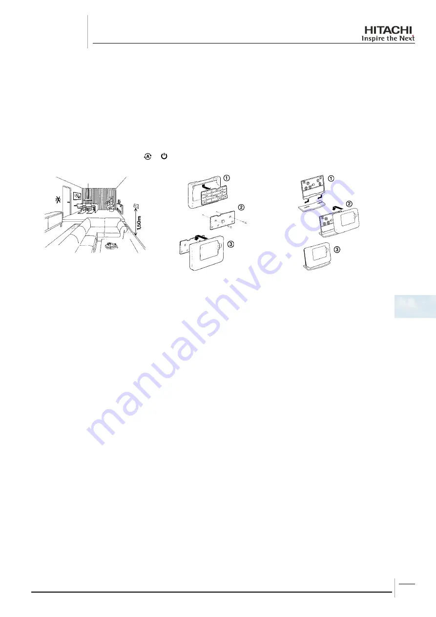
While still in the Test Mode, the Room Unit should be located taking the following into consideration and reviewing the
illustrations below:
Find a suitable location where the signal transmission is reliable. Reliable transmission is indicated when the RF
1.
Receiver is flashing the green LED every 6 seconds.
Install the
2.
room Unit
EITHER on the wall using the wall bracket OR attach the optional table stand as shown in below.
Exit the Test Mode by pressing the
3.
or button.
Wall bracket
Table stand
• The Room Unit should be installed in an open space for best performance as it is a radio frequency device.
• Leave at least 30cm distance from any metal objects including wall boxes and at least 1 meter from any other
electrical equipment as radio, TV, PC etc.
• Do not mount onto metal wall boxes.
• It is recommended that the RF Receiver is fully installed.
4.22.3. Communication loss
In the event of an RF communications loss, the LED on the RF Receiver will indicate which type of fault has occurred.
• If there is a communications fault between the RF Receiver and the Room Unit, then the LED on the RF Receiver will
flash red for 0.1 sec ON every three seconds.
• If there is a fault in communications between the boiler or System Controller, then the LED on the RF Receiver will flash
3 times quickly and then be off for three seconds.
• If there is more than one Room Unit installed, as in multi-zone systems for example, and communications is lost with one
zone, then the red LED on the RF Receiver will flash two times quickly and then be off for two seconds.
• If there is more than one Room Unit installed, as in multi-zone systems for example, and communications is lost with
both zones, then the red LED on the RF Receiver will flash once for 0.1 sec ON, and 0.9 sec OFF.
Once the faulty device has been identified, replace as necessary and follow the re-binding procedure as described in section
Binding / Rebinding Procedure.
Содержание RHUE-3AVHN
Страница 1: ...Air to water Heat pump RHUE 3AVHN RHUE 4AVHN RHUE 5A V HN RHUE 6A V HN YUTAKI SERIES RHUE A V HN ...
Страница 2: ......
Страница 4: ......
Страница 6: ......
Страница 16: ......
Страница 34: ......
Страница 70: ......
Страница 166: ......
Страница 236: ...Spare parts Service Manual 234 Spare parts of Yutaki SMGB0066 rev 0 12 2009 8 2 2 DHWT Domestic Hot Water Tank ...
Страница 238: ......
Страница 260: ......
Страница 261: ......
Страница 262: ...SMGB0066 rev 0 12 2009 Printed in Spain ...


