L100 Inverter
Conf
igur
ing
Dr
iv
e P
a
ra
m
e
ters
3–27
NOTE:
To disable parameter editing when using B_31 lock modes 00 and 01, assign the
[SFT] function to one of the intelligent input terminals.
See
.
“B” Function
Run
Mode
Edit
Defaults
Func.
Code
Name /
SRW Display
Description
–FE
(CE)
–FU
(UL)
–FR
(Jpn)
Units
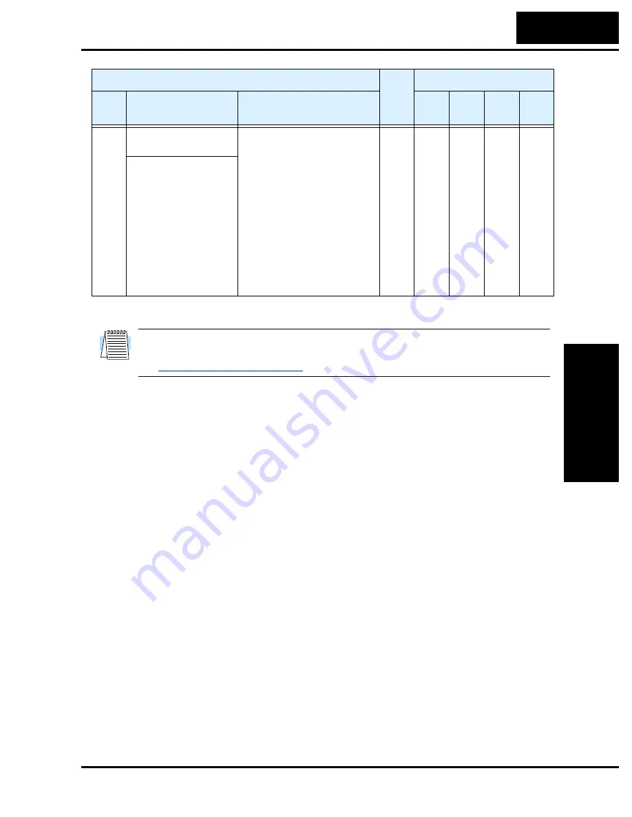
B_31 Software lock mode
selection
Prevents parameter changes, in
four options, option codes:
00 ...all parameters except
B_31 are locked when [SFT]
terminal is ON
01 ...all parameters except
B_31 and output frequency
F01 when SFT from terminal is
ON
02 ...all parameters except
B_31 are locked
03 ...all parameters except
B_31 and output frequency
F_01 setting are locked
✘
01
01
01
—
S-LOCK MD1
Содержание L100 Series
Страница 145: ...Inverter System Accessories In This Chapter page Introduction 2 Component Descriptions 3 Dynamic Braking 5 5 ...
Страница 168: ...Glossary and Bibliography In This Appendix page Glossary 2 Bibliography 8 A ...
Страница 176: ...Drive Parameter Settings Tables In This Appendix page Introduction 2 Parameter Settings for Keypad Entry 2 B ...
Страница 183: ...CE EMC Installation Guidelines In This Appendix page CE EMC Installation Guidelines 2 Hitachi EMC Recommendations 6 C ...
Страница 186: ...CE EMC Installation Guidelines Appendix C C 4 L1 L2 L3 PE M 3 L100 inverter with footprint type filter ...
Страница 187: ...L100 Inverter Appendix C C 5 L1 L2 L3 PE L100 inverter with book type filter M 3 ...


