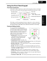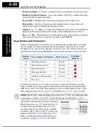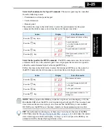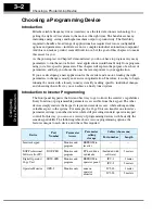
“F” Group: Main Profile Parameters
Configur
ing
Dr
iv
e P
a
ra
m
e
ters
3–8
“F” Group: Main Profile Parameters
The basic frequency (speed) profile is
defined by parameters contained in the “F”
Group as shown to the right. The set
running frequency is in Hz, but accelera-
tion and deceleration are specified in the
time duration of the ramp (from zero to
maximum frequency, or from maximum
frequency to zero). The motor direction
parameter determines whether the keypad
Run key produces a FWD or REV command. This parameter does not affect the intelli-
gent terminal [FWD] and [REV] functions, which you configure separately.
Acceleration 1 and Deceleration 1 are the standard default accel and decel values for the
main profile. Accel and decel values for an alternative profile are specified by using
parameters A_92 through A_93. The motor direction selection (F_04) determines the
direction of rotation as commanded only from the keypad.
Output
frequency
F 01
F 02
F 03
t
0
“F” Function
Run
Mode
Edit
Defaults
Func.
Code
Name /
SRW Display
Description
–FE
(CE)
–FU
(UL)
–FR
(Jpn)
Units
F_01
Output frequency
setting
Standard default target
frequency that determines
constant motor speed,
range is 0 to 360 Hz
✔
0.0
0.0
0.0
Hz
TM 000.0 0.0Hz
F_02
Acceleration 1 time
setting
Standard default acceleration,
range is 0.1 to 3000 sec.
✔
10.0
10.0
10.0
sec.
ACC 1 0010.0s
F_03
Deceleration 1 time
setting
Standard default deceleration,
range is 0.1 to 3000 sec.
✔
10.0
10.0
10.0
sec.
DEC 1 0010.0s
F_04
Keypad Run key routing Two options; select codes:
00... Forward
01... Reverse
✘
00
00
00
—
INIT DOPE FWD
Содержание L100 Series
Страница 145: ...Inverter System Accessories In This Chapter page Introduction 2 Component Descriptions 3 Dynamic Braking 5 5 ...
Страница 168: ...Glossary and Bibliography In This Appendix page Glossary 2 Bibliography 8 A ...
Страница 176: ...Drive Parameter Settings Tables In This Appendix page Introduction 2 Parameter Settings for Keypad Entry 2 B ...
Страница 183: ...CE EMC Installation Guidelines In This Appendix page CE EMC Installation Guidelines 2 Hitachi EMC Recommendations 6 C ...
Страница 186: ...CE EMC Installation Guidelines Appendix C C 4 L1 L2 L3 PE M 3 L100 inverter with footprint type filter ...
Страница 187: ...L100 Inverter Appendix C C 5 L1 L2 L3 PE L100 inverter with book type filter M 3 ...

