L100 Inverter
Oper
ations
and Monitor
ing
4–15
External Trip
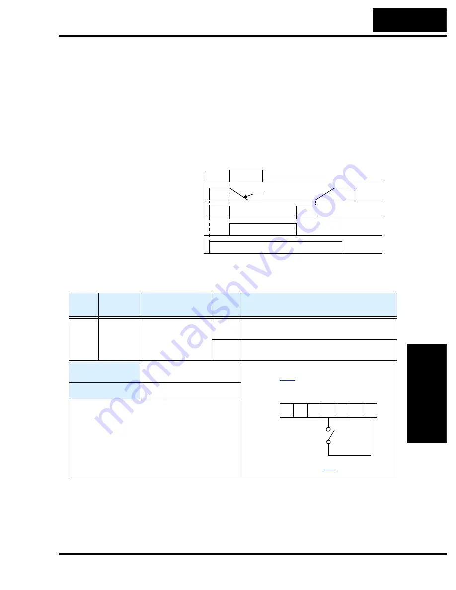
When the terminal [EXT] is turned ON, the inverter enters the trip state, indicates error
code E12, and stops the output. This is a general purpose interrupt type feature, and the
meaning of the error depends on what you connect to the [EXT] terminal. Even if the
[EXT] input is turned OFF, the inverter remains in the trip state. You must reset the
inverter or cycle power to clear the error, returning the inverter to the Stop Mode.
In the graph below, the [EXT] input turns ON during normal Run Mode operation. The
inverter lets the motor free-run to a stop, and the alarm output turns ON immediately.
When the operator initiates a Reset command, the alarm and error are cleared. When the
Reset is turned OFF, the motor begins rotation since the Run command is already active.
[EXT] terminal
RUN command [FW, RV]
[RS] terminal
Motor revolution speed
Alarm output terminal
t
free run
1
0
1
0
1
0
1
0
1
0
Option
Code
Terminal
Symbol
Function Name
Input
State
Description
12
EXT
External Trip
ON
When assigned input transitions OFF to ON,
inverter latches trip event and displays E12
OFF
No trip event for ON to OFF, any recorded trip
events remain in history until Reset
Valid for inputs:
C_01, C_02, C_03, C_04,
C_05
Required settings:
(none)
Notes:
•
If the USP (Unattended Start Protection) feature is
in use, the inverter will not automatically restart
after cancelling the EXT trip event. In that case, it
must receive either another Run command (OFF-
to-ON transition), a keypad Reset command, or an
[RS] intelligent terminal input signal.
Example (requires input configuration—
see page
):
See I/O specs on page
1
2
3
4
5
L
P24
EXT
Содержание L100 Series
Страница 145: ...Inverter System Accessories In This Chapter page Introduction 2 Component Descriptions 3 Dynamic Braking 5 5 ...
Страница 168: ...Glossary and Bibliography In This Appendix page Glossary 2 Bibliography 8 A ...
Страница 176: ...Drive Parameter Settings Tables In This Appendix page Introduction 2 Parameter Settings for Keypad Entry 2 B ...
Страница 183: ...CE EMC Installation Guidelines In This Appendix page CE EMC Installation Guidelines 2 Hitachi EMC Recommendations 6 C ...
Страница 186: ...CE EMC Installation Guidelines Appendix C C 4 L1 L2 L3 PE M 3 L100 inverter with footprint type filter ...
Страница 187: ...L100 Inverter Appendix C C 5 L1 L2 L3 PE L100 inverter with book type filter M 3 ...


