www.hi-velocity.com
© 1995-2017 Energy Saving Products Ltd.
*To adjust the remaining T-Stat settings:
- Jumper between R & the desired T-Stat setting
- Adjust the corresponding trimpot to the desired airflow using the
method described in the
System Commissioning and Set-Up
.
N
Fig. 003
Fig. 004
Fig. 005
Fig. 006
Ensure
Transformer
is
connected properly
Inspect
Supply Voltage
Supply Power
present?
Verify that
24VAC
is
present between
C &
desired T-Stat
setting
Input Voltage
and
T’Stat function
on PSB is functioning correctly
Verify that
Pressure Sensing
section of PSB is functioning
within proper operating range
Blue Light (L2)
present on
PSB
Circuit Board
?
Voltage present
? (0-10VDC)
VDC < 9VDC
Read and record
Volts DC Value
Adjust trimpot
1/2 turn Counter-Clockwise
Read and record
Volts DC value
to confirm adjustment
VDC
changed
?
PSB Circuit Board
is
functioning correctly
Adjust trimpots
on PSB Circuit
Board until airflow is
running at desired speed
*See
System Commissioning
Report and Set-Up
Ensure that
Jumper
is installed correctly
(Fig. 002)
Turn appropriate
PSB trimpot
1/2 turn Counter-Clockwise
,
wait 30-45 seconds for
drive to adjust -
Return to
Step 9
Ensure that
Volt Meter
is set to
read Volts DC.
Test Voltage
on
opposite end of cable
(Fig. 006)
Decrease PSB trimpot of
jumpered tstat setting
1/2
turn Counter-Clockwise
-
Wait 30 seconds for
drive to adjust
(Fig. 007)
Adjust trimpot
1/2 turn
Counter-Clockwise
,
wait 30 seconds -
VDC changed
?
Return to
Step 4
Replace
Transformer
Turn off
Supply Power,
connect
Transformer
, turn on
Power
- Return to
Step 5
Call Technical Support
Toll Free 1-888-652-2219
Install Jumper
and
return to
Step 6
Voltage
present?
Continue adjustments
until
VDC < 9VDC
(Again) Adjust
1/2 turn
Counter-Clockwise
,
wait 30 seconds -
VDC changed
?
Return to
Step 15
Return to
Step 13
Change
PSB Circuit Board
Return to
Step 11
Call Technical Support
Toll Free 1-888-652-2219
10
9
8
7
6
5
4
Verify that
Main Supply Voltage
is
present on the PSB circuit board
between the
L and N terminals
(Fig. 003)
3
Power
Fan Coil
2
11
17
16
15
14
13
18
N
Y
Y
Y
Y
N
N
N
N
N
N
12
Y
Y
Y
N
Y
Y
N
N
Y
N
Y
Verify that
24VAC
is
present between
R & C
on
the PSB circuit board
(Fig. 004)
Return to
Step 12
Y
Cooling
(Y2 terminal)
Heating
(W2 terminal)
Recirc Fan
(G terminal)
Fig. 007
Fig. 002
Fig. 001
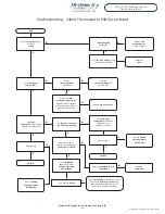
Troubleshooting - Motor Running Too Fast
1
Jumper desired Tstat setting
with
R on the PSB Circuit Board
(Figs. 001-002)
-43-
Module HE-Z DIA Diagnostics &
Trouble Shooting (2/8)
Module DIA Diagnostics & Trouble Shooting (2/8)
Verify that
Pressure Sensing
section
of PSB is functioning properly
by measuring
Voltage Output
(Volts DC) @ the WEG controller,
Terminals 7 & 8
(Fig. 005)
Start


