www.hi-velocity.com
© 1995-2017 Energy Saving Products Ltd.
Location
When locating the plenum duct, one of the main factors to
consider is the integration of the duct work into the structure.
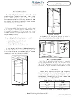
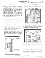
The main supply duct can be located along the main beam(s) in
the basement (Fig. DUC-01).
Fig. DUC-01 - Basement Installation
Min. 18”
(457mm)
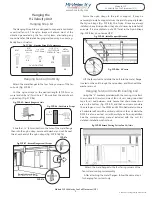
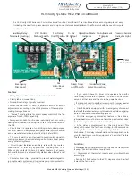
The main plenum can also be easily installed in the attic
space. (Fig. DUC-02)
Fig. DUC-02 - Attic Installation
18”
(457mm)
If the unit is installed in the attic, make sure that all ducts in
the attic are insulated with a vapour barrier.
All A/C systems main plenums need to be
insulated and vapour barriered.
Check with local codes for required R-Value. This includes the
Branch Take Off and the vent Rough-In Boot. All main plenum
and flex runs should be installed under the attic insulation. If the
duct work is run above the attic insulation, an extra insulation
sleeve may be needed. Check your local building code for the
ruling in your area.
For any duct runs over 75% of the maximum allowable
plenum length (Module SPC - Specifications and Sizing Pgs. 1,
2), it is recommended to insulate the main plenum. Insulating
the main plenum will cut down on your duct loss, and form a
vapour barrier. The attic insulation should be placed over all Hi-
Velocity System ducts to further reduce any duct losses.
Main Plenum Connectors
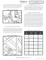
There are five types of connections that are possible with the
Hi-Velocity System.
All of the connections are done as follows. Place the joint
connector, cap, tee, or elbow inside the plenum you intend to
connect. Push the plenum over the fitting as tight as possible.
Use four screws on each side of the connector, alternating the
screw locations as indicated in Fig. DUC-04.
Fig. DUC-03 - Connectors
1. Tee Connection
2. Elbow Connection
3. Reducers
4. End Cap
5. Straight Connection
Fig. DUC-04 - Alternating screw locations
Elbow and Tee Placement
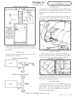
Elbows and tees must not be placed any closer than 18” from
supply outlet on the air handling unit. A significant loss of airflow
can result if elbows or tees are installed closer than 18” (457mm).
Figs. DUC-06 and Fig. DUC-07 illustrate a proper install with at
least 18” of straight plenum after the unit supply outlet. Fig.
DUC-05 shows the sigma velocity profile of the first 18” (457mm)
of the main plenum and why it’s important to allow the system
to equalize air flow.
IF THE DUCT IS LOCATED IN AN UNCONDITIONED AREA,
INSULATING SLEEVE IS REQUIRED ON THE MAIN PLENUM.
IF USED FOR COOLING, IT IS ALSO RECOMMENDED TO
INSULATE AND VAPOR BARRIER THE MAIN PLENUM AND
FLEX DUCT FITTINGS. INSULSLEEVES ARE AVAILABLE AS
AN ACCESSORY IN R4.2 AND R4.8 FOR 6”
(150mm)
, 8”
(200mm)
OR 10”
(255mm)
PLENUMS IN 10’
(3.05m)
LENGTHS.
Flexible duct is NOT to be used for
supply air plenum.
Plenum Duct
Module DUC
Installing Plenum and Branch Duct (1/9)
Module DUC Installing Plenum and Branch Duct (1/9)
Insul-Sleeve
over plenum
-10-


