www.hi-velocity.com
© 1995-2017 Energy Saving Products Ltd.
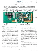
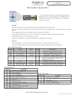
The Hi-Velocity HE-Z Series Fan Coil utilizes a dual function Circuit Board. This circuit board makes zoning simple and easy,
eliminating the need for by-pass dampers and dump zones. It also makes adjustment to airflow quick with the use of trim pots
for direct control.
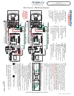
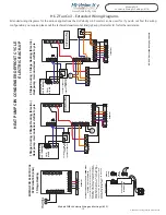
Hi-Velocity Systems HE-Z PSB Circuit Board
Module WIR
Hi-Velocity Wiring & Settings (1/10)
Module WIR Hi-Velocity Wiring and Settings (1/10)
Features:
•
Wiring the circuit board is a quick and simple task.
• Clearly labeled connections.
• No additional relays typically required.
•
When the PSB is set to “Auto”, it allows for automatic airflow
adjustments, according to the static pressure of the supply air,
making zoning a breeze.
•
“Manual” mode allows for direct speed control of the fan
anywhere from 0-100% capability.
•
Fan speeds in both functions are individually set for cooling,
heating and constant fan using the three trim pots located on
the PSB.
•
Circuit board is capable of controlling boilers, dual purpose
hot water heaters, heat pumps, and geothermal systems, as well
as our manufactured slide-in electric strip heaters (ESH).
• The circuit board is also designed to send control signals to
cooling sources such as condensing units, chillers, heat pumps
and geothermal systems.
•
Circuit board features an auxiliary relay with dry contacts
connections, so that any applications requiring 24v, 120v,
230v or dry contacts (boilers, hot water heaters, heat pumps
& humidifiers) can be automatically started when there’s a call
for heat.
• Circulator timer chip is provided to prevent water stagnation
in potable water systems and to provide pump rotor protection
for water source heating and cooling.
Auxiliary Relay
Terminals (Heating)
VDC Control
Method Switch
Pressure Sensor
Indicator Light
Fan Adjustment
Trimpots
Operation Mode
Indicator
0 - 10v
DC Output
Fan Delay
On/Off Switch
T’Stat
Connections
24v
Auto-Reset
Fuse
Condenser/Zone
Valve Connections
Pump Timer
on/off Switch
Emergency
Disconnect
-21-
•
If you wish to have the timer cycle operate at a specific
time of day, simple turn off power to the fan coil unit for ten
seconds at that time and then turn the power back on.
•
If you do not need to use the timer, move the jumper header
from the On pins to the Off pins and it will be disabled.
• Circuit board is equipped with an emergency disconnect
feature. If there’s an emergency this feature will de-energizing
all fan speeds and connected equipment.
•
For this emergency disconnect feature to be active a
jumper header must be remove from the pins located close
to the emergency disconnect terminal strip.
•
A fan delay is programmed into the circuit board. This
delay will prevent the fan from starting for 20 seconds on
cooling, 30 seconds on heating, and purge for 30 seconds on
shut-down. This delay is beneficial in certain applications to
give the heating or cooling equipment a “head start” before
the fan turns on.
Function:
•
Manages input power and through the use of a transformer
it supply 24vac to additional equipment.
• Organizes all thermostat inputs and prioritizes them
accordingly.
•
Sends a 0-10vdc output to the VFD, dependent on how fast
it wants the fan to run.

