www.hi-velocity.com
© 1995-2017 Energy Saving Products Ltd.
Operation
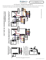
The low voltage signals that energize the ESH come from the air
handler’s zone valve terminals (W1/W2 output and C). These are
to be connected to #1 and #2 of the ESH. Note: This connection
is polarity sensitive. The W2 output is energized with 24v with a
call for heat from a W2 call on the air handler’s terminal board.
W2 will also energize the heating fan speed on the air handler.
For air handler to ESH low voltage wiring, see next page. High
voltage wiring of the ESH can be viewed on the inside of the ESH
front panel.
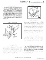
On a demand for heat the TH-24 electronic sequencer will
energize the heating elements in sequence. When the thermostat
is satisfied, all the elements and blower will be de-energized.
Within the ESH, there are automatic reset thermal cut-out
disc type safety devices at a fixed temperature that open the
control circuit when a set point is reached. When the overheating
conditions have disappeared, it automatically resets and returns
the heater to normal operating conditions.
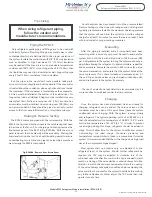
Zoning
The standard off the shelf ESH has 2 stages and
therefore can be used with a maximum of 2 zones.
Energy
Saving Products Ltd. also offers a special electric strip module
for increased zoning capabilities. Please contact the factory for
additional information.
Maintenance
ESH heaters have been designed to operate long term without
issue. Those responsible for equipment and maintenance should
be aware of the following suggestions:
Periodic visual inspection: This precautionary step will help to
keep your unit operating properly. Inspect the unit periodically and
be on the lookout for any first signs of problems: Accumulation of
dust on the heating elements, signs of overheating on the heater
frame, traces of water or rust on the control box.
Electrical inspection: Two weeks after start up, all electric
connections to contactors should be re-checked and tightened.
Before each heating season, the following steps are recommended:
•
Check all fuses
•
Check resistance to ground for each circuit
•
Check resistance phase to phase for each circuit
•
Check the tightness of connections at all contactors
and heating elements
•
Check all contactors
•
Check electrical connections to heating elements,
magnetic contactors, and main power plugs.
It is recommended that this inspection be performed monthly
for the first four months of operation. Following that, two
inspections per heating season is sufficient.
Off Season Maintenance
Should a heater be shut off for a long period, we recommend
that you carefully check the resistance to ground for each circuit.
It is important not to power a heater when too low a resistance
to ground has been measured. It is also recommended to pay
attention to any other heater operating in normal conditions.
All control components should be maintained and checked
according to respective manufacturer’s instructions. Any defective
components should be replaced only with identical origin parts.
Module ESH
Electrical Strip Heater Installation (2/2)
Module ESH Electrical Strip Heater Installation (2/2)
-39-
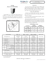
Specifications
ESH - 650
ESH - 750
ESH - 1100
Matching Fan Coil
(1)
HE-Z/HE-B/HE/HV-50/51 BU
LV-50 BU
HE-Z/HE-B/HE/HV-70/71 BU
LV-70 BU,
LV-Z/LV-E-1050 BU
HE-Z/HE-B/HE-100/101 BU
LV-120/140 BU
Part Numbers
5kw - 10025650005
5kw - 10025750005
10kw - 10025110010
10kw - 10025650010
10kw - 10025750010
15kw - 10025110015
15kw - 10025650015
15kw - 10025750015
18kw - 10025110018
18kw - 10025750018
20kw - 10025110020
23kw - 10025110023
Volts
240
240
240
Phase
1
1
1
Shipping Weight
21 lbs
(9.5kg)
27 lbs
(12kg)
28 lbs
(13kg)
Module Size
(2)
(L x W x H)
13
3
/4
”
x
5
5
/8
”
x
15
1
/2
”
(349mm x 143mm x 394mm)
18
3
/4
”
x
5
5
/8
”
x
15
1
/2
”
(476mm x 143mm x 394mm)
24
3
/4
”
x
5
5
/8
”
x
15
1
/2
”
(629mm x 143mm x 394mm)
(1) Electrical Strip Heating not available for JH Series or LV-Z/LV-E-1750
(2) Dimensions for the ESH do not include the electrical access panel, add 4” to ESH for Total Length


