Important Safety Notices
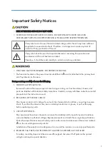
• RISK OF ELECTRIC SHOCK DO NOT OPEN
• TO REDUCE THE RISK OF ELECTRIC SHOCK, DO NOT REMOVE COVER. NO USER-
SERVICEABLE PARTS INSIDE. REFER SERVICING TO QUALIFIED SERVICE PERSONNEL.
This symbol warns the user that uninsulated voltage within the unit may have sufficient
magnitude to cause electric shock. Therefore, it is dangerous to make any kind of
contact with any part inside of this unit.
This symbol alerts the user that important literature concerning the operation and
maintenance of this unit has been included.
Therefore, it should be read carefully in order to avoid any problems.
• HEAT SINK MAY BE ENERGIZED. TEST BEFORE TOUCHING.
• The heat sink located on the power board is electrified. A mark is attached to the primary heat
sink. Pay attention to this area.
During servicing carefully observe the following.
1. OBSERVE ALL PRECAUTIONS
Items and locations that require special care during servicing, such as the cabinet, chassis, and
parts are labelled with individual safety instructions. Carefully comply with these instructions and all
precautions in the instruction manual.
2. BE CAREFUL OF ELECTRIC SHOCK
The chassis carries an AC voltage. If you touch the chassis while it is still live, you will get a severe
shock. If you think the chassis is live, use an isolating transformer or gloves, or pull out the plug
before replacing any parts.
3. USE SPECIFIED PARTS
The components have been chosen for minimum flammability and for specific levels of resistance
value and ability to withstand voltage. Replacement parts must match these original specifications.
Parts whose specifications are particularly vital to safe use and maintenance of the set are marked
on the circuit diagrams and parts list.
Substitution of these parts can be dangerous for you and the customer, so use only specified parts.
4. REMOUNT ALL PARTS AND RECONNECT ALL WIRES AS ORIGINALLY INSTALLED
For safety, insulating tape and tubes are used throughout, but some lift-off parts on the printed
wiring board require special attention.
1
Содержание Sirius-PJ2
Страница 1: ...Model Sirius PJ2 Machine Codes Y076 Y077 Y078 Field Service Manual June 2015 ...
Страница 2: ......
Страница 12: ...10 ...
Страница 13: ...1 Product Information Specifications See Appendices for the following information General Specifications 11 ...
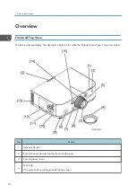
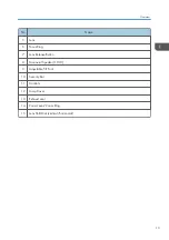
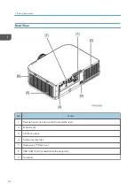
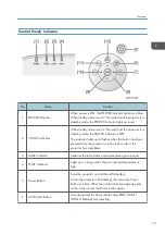
Страница 20: ...No Name 16 Ethernet Port RJ 45 Part Names of the Remote Controller 1 Product Information 18 ...
Страница 24: ...1 Product Information 22 ...
Страница 34: ...Filters 1 Remove the Filter cover A 2 Remove the Filters A 3 Replacement and Adjustment 32 ...
Страница 36: ...5 Disconnect the cable 1 PCB Key Pad 1 Top cover page 33 3 Replacement and Adjustment 34 ...
Страница 37: ...2 Remove the Holder A 2 3 Remove the PCB Key Pad A 2 Front Cover 1 Top cover page 33 Parts Replacement 35 ...
Страница 38: ...2 Front Cover A 4 3 Remove the two connectors 2 PCB SCAP 1 Front Cover page 35 3 Replacement and Adjustment 36 ...
Страница 40: ...3 Release the tabs to remove the holder as below 4 Remove the connector 1 3 Replacement and Adjustment 38 ...
Страница 41: ...Lens Shift Dial 1 Remove the Lens Shift Dial A and spring Rear Panel 1 Top cover page 33 Parts Replacement 39 ...
Страница 52: ...4 Remove the bracket A 5 Remove the G LCD Fan A 2 6 Remove the cushion A 3 Replacement and Adjustment 50 ...
Страница 54: ...5 Remove the Duct Cover A 3 6 Remove the Duct Base A 3 3 Replacement and Adjustment 52 ...
Страница 67: ...3 Remove the bracket A 2 4 Remove the Power supply DC 6 Parts Replacement 65 ...
Страница 141: ...For Video Perform the following check after powering ON the projector Troubleshooting Guide 139 ...
Страница 145: ...Service Information Page 2 User mode Expert mode Service mode Display of lamp voltage added Error Log 143 ...
Страница 153: ...MEMO 151 ...
Страница 154: ...MEMO 152 EN ...
Страница 155: ...Model Sirius PJ2 Machine Codes Y076 Y077 Y078 Appendices June 2015 ...
Страница 156: ......
Страница 158: ...2 ...
Страница 172: ...MEMO 16 EN ...


