19
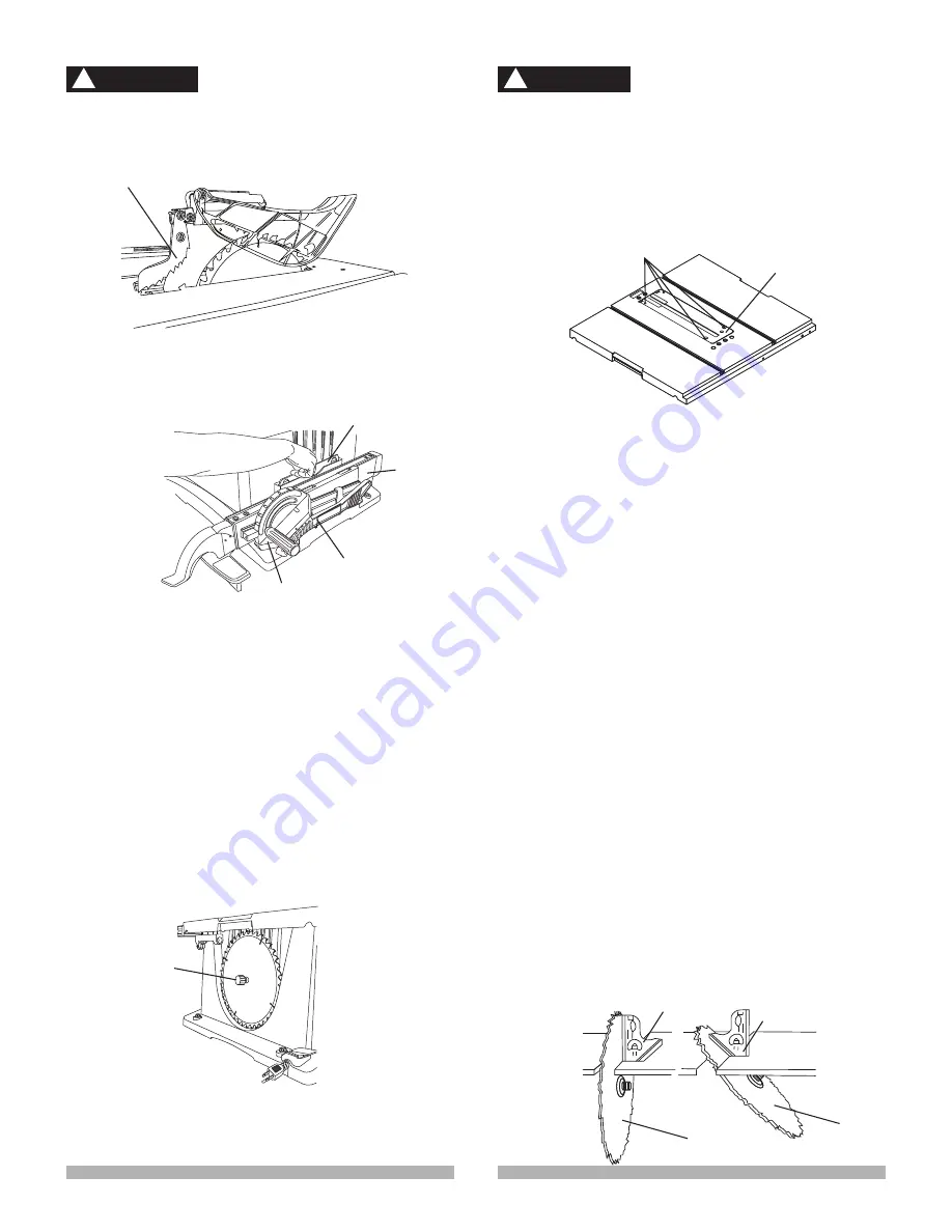
To avoid serious injury, the table insert (2) must be
level with the table. If the table insert is not flush
with the table, adjust the four bolts (1) with a 4 mm
hex wrench until it is parallel with the table.
NOTE:
To raise the insert, turn the hex screws
counterclockwise, to lower the insert, turn the hex
screws clockwise.
ADJUSTING THE 90° AND 45° POSITIVE STOPS
(FIG. W, X)
Your saw has positive stops that will quickly position the
saw blade at 90° and 45° to the table. Make adjustments
only if necessary.
90° Stop
1. Disconnect the saw from the power source.
2. Raise the blade to the maximum elevation.
3. Loosen the blade bevel lock handle and move the
blade to the maximum vertical position and tighten
the bevel lock handle.
4. Place a combination square (1) on the table and
against the blade (2) to determine if the blade is 90°
to the table. (Fig. W)
5. If the blade is not 90° to the table, loosen or tighten
(depending on whether you are increasing or
decreasing the degrees) the hex screw (3) with a 5
mm hex wrench until you achieve 90°. (Fig. X)
6. Loosen the bevel lock handle and reset the blade
at the maximum vertical position, then tighten the
bevel lock handle.
7. Check again to see if the blade is 90° to the table. If
not, repeat step 5.
8. Lastly, check the bevel angle scale. If the pointer
does not read 90°, loosen the screw holding the
pointer and move the pointer so it is accurate at 0°
and retighten the pointer screw.
Improper riving knife alignment can cause
“kickback” and serious injury.
INSTALLING THE PUSH-STICK STORAGE (FIG. T)
Attach the metal push-stick storage bracket (1) into the
provided slots on the right side of the body shell. The
bracket will snap into place.
STORAGE (FIG. T, U)
Rip fence, Mitre gauge (FIG. T)
Storage brackets for the rip fence (2) and mitre gauge (3)
are located on the right side of the saw housing.
NOTE:
Adjust the mitre gauge to 45°~60° before putting
away in storage.
Blade wrench (FIG. T)
Insert the handle of the blade wrench (4) into the slot
located to the right side of the saw housing.
Blade (Fig. U)
1. Loosen and remove the knob (1) on the left side of
the saw housing.
2. Place extra blades onto the arbour. Replace the
knob and tighten.
ADJUSTING THE TABLE INSERT (FIG. V)
The table insert is already installed on your unit.
However, you must verify that the table insert is flush
with the table top surface on all four corners of the insert.
1
1
4
2
3
1
2
Fig. T
Fig. U
Fig. V
WARNING
!
Fig. W
1
2
45°
90°
1
2
WARNING
!
Fig. S
Anti- kickback pawls
Содержание X-pert 89335002
Страница 11: ...11 UNPACKING YOUR TABLE SAW A B C D E F G H I J K L M N O P Q R S T U V W X Y ...
Страница 34: ...34 10 IN JOB SITE TABLE SAW MODEL NO JT2503RN SCHEMATIC MANUAL INSTRUCTION ...
Страница 36: ...36 10 IN JOB SITE TABLE SAW MODEL NO JT2503RN SCHEMATIC FOR STAND ...
Страница 38: ...38 ...


