Harsco Industrial P-K SONIC SC-3000 Скачать руководство пользователя страница 17

31

Harsco Industrial, Patterson-Kelley Technical Service 1.877.728.5351

M

a

INT
e

N

a

NC
e

Gas Fired Boiler

30

Harsco Industrial, Patterson-Kelley Technical Service 1.877.728.5351

M

a

INT

e

N

a

NC

e

Gas Fired Boiler

1. When the Boiler On/Off switch is turned on, power is provided through a circuit 

breaker to the boiler control and the combustion blower.
2. If the high gas, low gas or low water level control is open, the boiler control 

locks out and displays an error.
3. When the water temperature is below the boiler control setpoint minus the 

hysteresis (On Differential), a heat request is generated.
4. Provided all limits are made, the boiler will attempt to start.
5. The controller checks that the air pressure switch is open indicating no airflow. 

The blower is driven towards the prestart fan speed. When the air pressure 

switch closes, the 25 second pre-purge time is started. After the pre-purge, the 

blower is driven to the ignition speed.
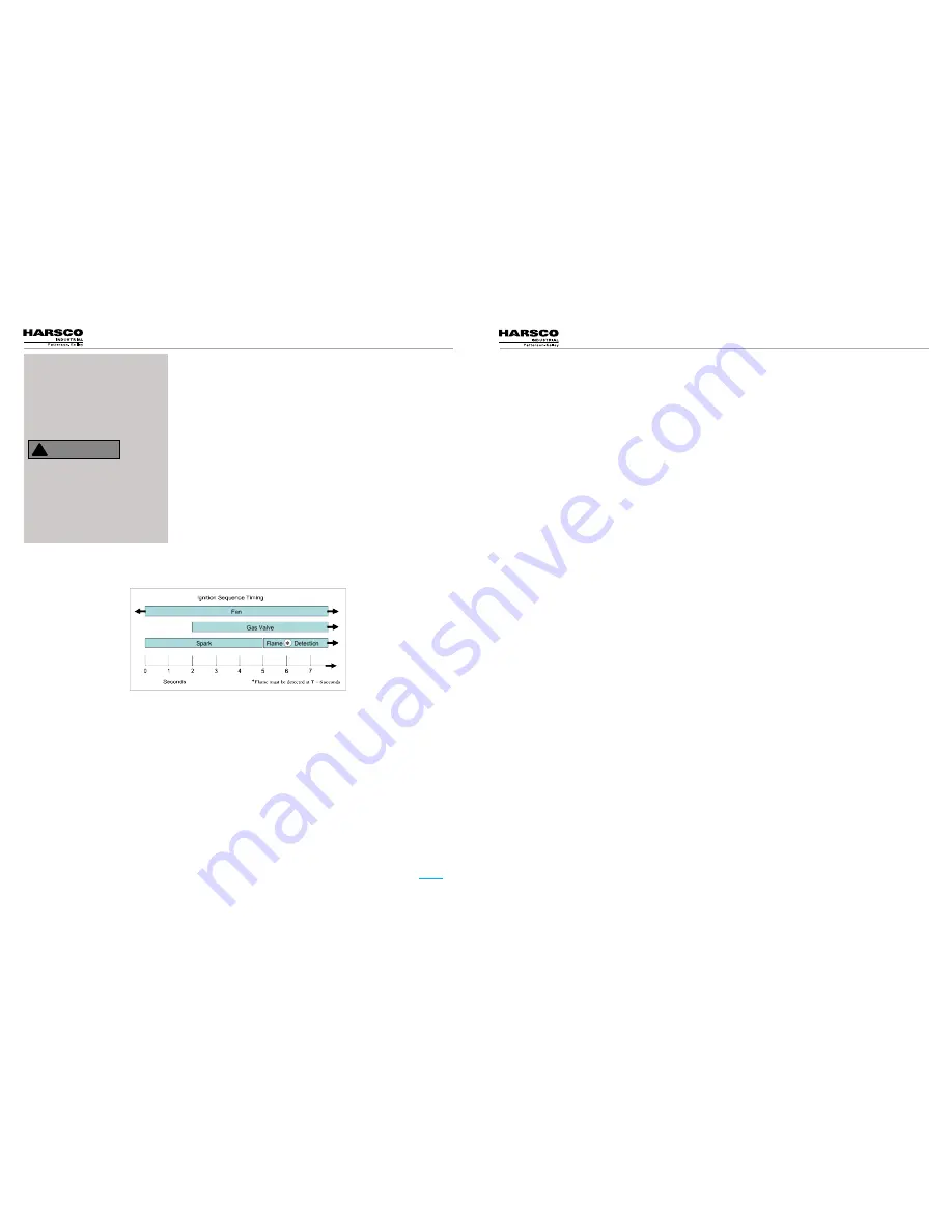
6. A trial for ignition begins. The sequence of events is illustrated graphically 

below.
7. After ignition, the fan may be driven to low fire before the boiler is released to 

modulation.
8. The control modulates the firing rate between low and high fire to maintain the 

desired outlet water temperature.

9. The burner will continue firing until the outlet water temperature reaches set point plus hysteresis (Off Differential). At this 

temperature the fuel supply is shut off and the combustion air fan continues to run for a 30 second post-purge.
10. When the water temperature is reduced by the load on the system, a heat request is generated. The operating sequence 

will recycle to 

Step 4

.

The ENVI® boiler control will display text based error descriptions to indicate any problems with the boiler. There 

are two types of lockouts the control may experience: manual reset lockouts requiring an operator to press the 

reset button, and automatic reset lockouts that will self reset when the error condition clears. A listing of errors 

and their service codes is included at the end of this section.
Should the unit fail to operate, call a qualified service technician to troubleshoot the problem and implement 

corrective actions.

5.6.1 loss of Power

In the event of a power failure, the display panel is not illuminated and the entire system is de-energized, closing 

all automatic valves and halting all boiler operations. When power is restored the sequence of operation will 

resume at 

Step 4

. If any error/lockout is present when the power is lost, the control will retain that error/lockout 

and display the error/lockout when the power is restored.

5.6.2 Loss of Water Level

The low water switch opens when there is insufficient water level in the boiler. Lockout 

LOW WATER LEVEL 

is 

shown on the display, the burner operation is interrupted, and the boiler locks out. When the correct water level is 

re-established, and the control reset button is pressed, the boiler will reset and will start the sequence at 

Step 4

5.5 s

eQuenCe


of

 o

peraTIon

n

oTICe

!

Once the boiler begins the ignition 

sequence, the firing sequence will 

continue until main flame is reached


regardless of heat request. The 

sequence can be interrupted by 

turning the power switch off.

If any “Manual Reset” limit device 

trips, 

DO NOT

 reset without 

determining and correcting the 

cause. Manual Reset Limits 

include: Flame safeguard, high or 

low gas pressure, high temperature 

limit, stack temperature, low water 

level.

!

WARNING

5.6 T

roubleshooTIng

5.6.3 low Gas Pressure

The low gas pressure switch opens when there is (or has been) insufficient gas pressure available for proper 

operation of the boiler. If an external gas-supply shut-off valve is closed for any reason, a low gas condition will 

result. Locking 

LOW GAS PRESSURE

 is shown on the display, the burner operation is interrupted, and the boiler 

locks out. When proper gas pressure is restored, and the control reset button is pressed, the boiler will reset and 

will start the sequence at 

Step 4

5.6.4 high Gas Pressure

The high gas pressure switch opens when there is (or has been) excessive gas pressure for the proper operation 

of the boiler Locking 

HIGH GAS PRESSURE

 is shown on the display, the burner operation is interrupted, and the 

boiler locks out. When proper gas pressure is restored, and the control reset button is pressed, the boiler will 

reset and will start the sequence at 

Step 4

.

5.6.5 high Water temperature

When the boiler water has exceeded both the operating and high-limit temperature the high limit switch 

opens, and Locking 

HIGH LIMIT

 is shown on the display. When the water temperature falls below the high-limit 

temperature, the boiler will remain locked out until the water high limit switch is manually reset and the front panel 

reset button is pressed. Once reset, the control will restart the sequence of operation at 

Step 4

.

5.6.6 low Air

If the display panel indicates Locking 

AIR SWITCH NOT OPEN

 or Locking 

AIR SWITCH NOT CLOSED

 this indicates 

improper airflow through the boiler. Check the hoses leading to the air switches. Verify proper blower operation. 

An air switch error does not necessarily mean that the air switch is defective. 
When 

AIR SWITCH NOT OPEN

 is shown on the display, check that the air switch is open when the fan is off. 

Check that there is no air flow through the boiler when the fan is off.
When 

AIR SWITCH NOT CLOSED

 is shown on the display, check that the air switch is closed when the fan is 

running. If the air switch does not close within 5 minutes during purge, the boiler locks out. Check that the burner 

is clean ("Cleaning the Burner," 

Section 5.2

) and that there are no obstructions to airflow in the intake or exhaust 

ducts.

5.6.7 Flame Failure

In the event of a flame failure, the main fuel valves are de-energized and a manual reset lockout occurs. Locking 

IGNITION FAILURE

 or Lockout 

FLAME FAILURE

 is shown on the display. The cause of flame failure must be 

diagnosed and repaired before the control is reset.
When 

IGNITION FAILURE

 is shown on the display, the boiler did not light during a trial for ignition. Check that the 

spark, electrode, ignition wire, and gas valve are functioning properly.
When

 FLAME FAILURE

 is shown on the display, the boiler lost the flame during run. Check that the combustion is 

setup properly, the gas pressure is correct, as well as other combustion parameters.

5.6.8 Flame error

Locking 

LATE FLAME

Blocking 

FALSE FLAME


These errors signify flame error. This may be caused by a failed or leaky gas valve or a flame detector 

malfunction. If gas valve leakage is suspected, the unit must be isolated by turning off the main gas supply line. 

Qualified and knowledgeable service personnel must be called to evaluate and repair/replace the failed parts.

5.6.9 stack Problem

BLOCKED FLUE

 indicates that the high exhaust back pressure switch has tripped. This may be caused by a 

blocked stack, a blocked air inlet, or a blocked condensate system. When the blockage is removed, the boiler will 

automatically restart.

Figure 5.5

Содержание P-K SONIC SC-3000

Страница 1: ...ee 877 728 5351 Fax 570 476 7247 www harscopk com 2013 Harsco Industrial Patterson Kelley SONIC201 Revised June 12 2014 C S A Design Certified Complies with ANSI Z21 13 CSA 4 9 Gas Fired Low Pressure...

Страница 2: ...al connections for tightness as connections may come lose during shipping Venting Maintain exhaust pressure from 04 wc to 22 wc Hydronics Maximum Flow SC 4000 384 gpm SC 3000 285 gpm Minimum Flow Igni...

Страница 3: ...itches 23 3 10 Initial Adjustments 23 3 10 1 Operating Temperature Controller 23 3 10 2 Boiler Set Point 24 3 10 3 Other CH Parameters 24 3 10 4 Other Parameters 24 3 10 5 Additional Menu Items 24 3 1...

Страница 4: ...s fired boilers are fully modulating using variable speed combustion blowers sophisticated microprocessor controls modulating gas safety shut off control valves and a unique stainless steel heat excha...

Страница 5: ...res de verrouillage signalisation lors de l entretien WARNING Improper use may result in fire or injury Read instructions safety manual before installing operating or servicing boiler The safety label...

Страница 6: ...ainer and be covered by a tarpaulin or other waterproof covering 3 1 1 Initial Inspection Upon receiving the boiler inspect it for signs of shipping damage Some damage may be hidden Unpack the boiler...

Страница 7: ...connected to the DHW temperature sensor or thermostat This circuit is energized by the boiler with a 5V potential The temperature sensor must be a NTC having 12k 77 F Header Temp Sensor TB1 9 and TB1...

Страница 8: ...re that may cause excessive condensate production in the vent Direct Vent An appliance that is constructed and installed so that all air for combustion is derived directly from outdoors and all flue g...

Страница 9: ...d by deducting the blockage area of any fixed louvers grilles or screens from the total area of the opening 2 Screens shall be not smaller than 3 Motorized louvers shall be interlocked with the applia...

Страница 10: ...echnical Service 1 877 728 5351 INSTALLATION Gas Fired Boiler The boiler vent should not be connected into any portion of another mechanical draft system without consulting the vent manufacturer The b...

Страница 11: ...ll operate at maximum speed Do not operate a summer exhaust fan Close fireplace dampers 4 Place the appliance being inspected in operation Follow the lighting instructions Adjust the thermostat so tha...

Страница 12: ...tted to the boiler The boiler shall not be used as a pipe anchor When installed in a two pipe system that provides both chilled and hot water the control system should be configured so as to limit the...

Страница 13: ...guration 2 Place the boiler in operation at the high fire setting BNR TEST MODE HI 3 Smoothly close the downstream manual isolation valve to reduce the gas flow and cause flame failure 4 The display w...

Страница 14: ...hnician to hold the boiler in high or low fire during firing operation so that the combustion adjustment can be performed as indicated below The second test mode checks the fan rate with the burner of...

Страница 15: ...ssary 3 11 3 Checking Flame Signal Using the control panel enter the information mode and scroll down view the flame signal This shows A when the boiler is firing and shows 0 A when the boiler is not...

Страница 16: ...orrective action or repair 5 1 2 Weekly Observe the conditions of the main flame A normal high fire flame is mostly orange with a blue halo while at low fire the burner will glow yellowish orange Corr...

Страница 17: ...temperature low water level WARNING 5 6 Troubleshooting 5 6 3 Low Gas Pressure The low gas pressure switch opens when there is or has been insufficient gas pressure available for proper operation of...

Страница 18: ...INTERNAL ERROR 31 Internal Error 31 Call for service Code ENVI Display Lockout Description E01 OUT TEMP SENS OPEN Outlet Temperature Sensor Open Boiler outlet water temperature sensor open circuit E02...

Страница 19: ...o not ground through the conduit Terminal Number Label Description 3 120V AC Neutral Neutral for use with TB2 10 Switched Output 4 120V AC Neutral Neutral for use with TB2 11 3 Way Valve 5 120V AC Neu...

Страница 20: ...ly configured for either 208V 220 240V or 440 480V three phase 60 hertz service Improper configuration of the transformer could result in serious injury or death The high voltage TB2 terminal block is...

Страница 21: ...77 728 5351 Gas Fired Boiler 38 Harsco Industrial Patterson Kelley Technical Service 1 877 728 5351 Gas Fired Boiler PARTS TECHNICAL SUPPORT PARTS TECHNICAL SUPPORT SC 3000 SC 4000 220 240 VAC three p...

Страница 22: ...1 877 728 5351 Gas Fired Boiler 40 Harsco Industrial Patterson Kelley Technical Service 1 877 728 5351 Gas Fired Boiler PARTS TECHNICAL SUPPORT PARTS TECHNICAL SUPPORT 6 1 5 SC 3000 SC 4000 Boiler Wir...

Страница 23: ...lley Technical Service 1 877 728 5351 Gas Fired Boiler 42 Harsco Industrial Patterson Kelley Technical Service 1 877 728 5351 Gas Fired Boiler PARTS TECHNICAL SUPPORT PARTS TECHNICAL SUPPORT 6 1 5 2 S...

Страница 24: ...on Kelley Technical Service 1 877 728 5351 Gas Fired Boiler 44 Harsco Industrial Patterson Kelley Technical Service 1 877 728 5351 Gas Fired Boiler PARTS TECHNICAL SUPPORT PARTS TECHNICAL SUPPORT 6 1...

Страница 25: ...on Kelley Technical Service 1 877 728 5351 Gas Fired Boiler 46 Harsco Industrial Patterson Kelley Technical Service 1 877 728 5351 Gas Fired Boiler PARTS TECHNICAL SUPPORT PARTS TECHNICAL SUPPORT 6 1...

Страница 26: ...5 7 6 4 B 2 4 A Mark Description 1 Heat Exchanger 2 Blower Burner Assembly 3 Base 4 A Gas train LP 4 B Gas Train Natural Gas 5 Controller 6 Electrical Box 7 Front Door Control Panel 8 Cabinet 6 2 1 Ma...

Страница 27: ...Water Connection 5 Condensate Collector 6 Igniter 7 Burner 8 Burner Gasket 9 Burner Hood 6 2 3 SC 3000 SC 4000 Heat Engine Mark Description 1 Burner 2 Burner Transition Piece 3 Blower 4 Venturi 5 Manu...

Страница 28: ...cial or consequential damages such as loss of the use of products facilities or production inconvenience loss of time or labor expense involved in repairing or replacing the alleged defective Product...

Страница 29: ...Date Hi Low Fire O2 CO CO2 Stack Temp pH Action By Appendix 1 Maintenance Log 54 Harsco Industrial Patterson Kelley Technical Service 1 877 728 5351 APPENDIX 1 Gas Fired Boiler...

Страница 30: ...in section 3 10 4 to get 5 O2 in the flue gas If this cannot be achieved perform the following steps If the O2 is too high then the inlet gas pressure should be adjusted to the minimum pressure allow...

Страница 31: ...ntire hydronic system Samples of the system water with cleaner should be taken and analyzed to ensure proper cleaner strength Once cleaned the system should be flushed with fresh fill water until the...

Отзывы: