28
Hangar 9 F4U-1D Corsair 50 ARF
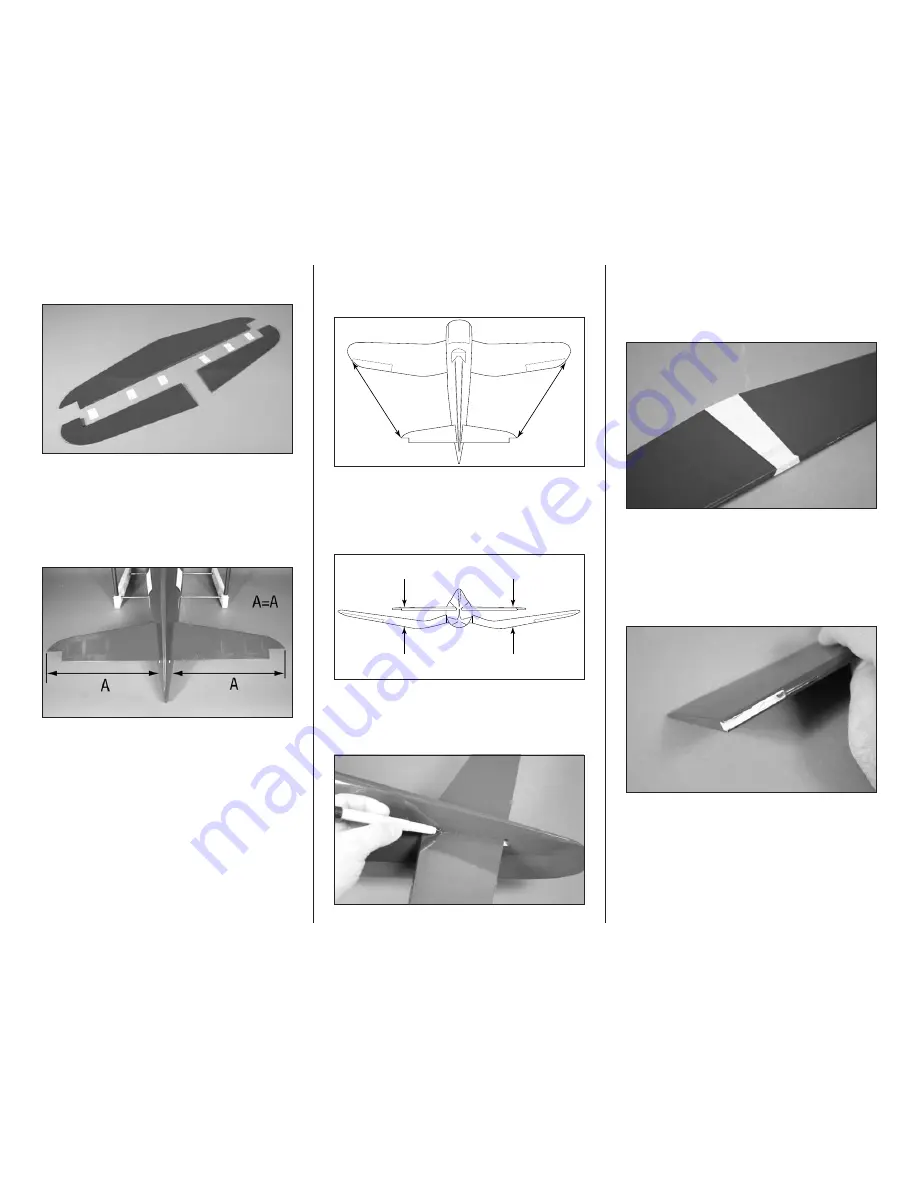
2. Separate the elevators from the stabilizer. Set the
elevators and six CA hinges aside.
3. Determine the top and bottom of the stabilizer by
inspecting the covering seam. The top covering overlaps
down, around and over the bottom covering. Slide the
stabilizer into the slot in the fuselage with the stabilizer as far
forward in the slot as possible, measure from the fuselage to
each tip. Center the stabilizer so the measurements are the
same.
6. Measure from stabilizer tip to the wing tip on both the
left and right side of the airframe. The measurement must
match exactly to align the stabilizer with the wing.
A
A
A=A
7. Stand back 8–10 feet (2–3 meters) and view the
aircraft from the rear. The wing and stabilizer must be an
equal distance from each other to be in alignment. If not,
use medium grit sandpaper to lightly sand the opening in the
fuselage to correct any alignment issues.
Check alignment
8. Double check the alignment of the stabilizer as
described in steps 5 through 7. Once set, use a felt-tipped
pen to trace the outline of the fuselage on the top and
bottom of the stabilizer.
9. Remove the stabilizer from the fuselage. Use a hobby
knife and a new #11 blade to trim the covering 1/16-inch
(1.5mm) inside the lines drawn in the previous step.
Remove the covering, exposing the wood at the center of the
stabilizer.
Note
: Make sure to use a new #11 blade and
use light pressure to trim only the covering.
Avoid cutting into the underlying wood, which
could weaken the structure of your model.
10. Use a hobby knife with a #11 blade to remove the
covering from the elevators for the 3mm metal joiner rod.


