background image


RTTY / FSK / AFSK  ICOM Cable 


MiniDin 8, DIN 8 
Cable Length  150 cm 


EzMaster Back Panel View 

DIN 8 


MiniDin 8 


Содержание EZMaster

Страница 1: ...5 04 Apr 2006 The EZMaster is manufactured in the EU Copyright 2003 2006 by HamRadioSolutions Co Inc All Rights Reserved Contents of this publication or the firmware within the EZMaster may not be rep...

Страница 2: ...een changed since last edition of this guide Changes from v 01 04 Minor spelling corrections throughout the whole text New Chapter Quick Start Guide on page 21 Record here your EZMaster serial number...

Страница 3: ...operly terminated connected to the connector shell This is usually accomplished by the use of a metal or back metalized plastic shell but may be implemented by direct contact including soldering with...

Страница 4: ...Interface 9 Isolated Audio Output 9 PTT Output 9 Radio Interface 10 Antenna Relays Output 10 Parallel Band Decoder 10 Microphone 10 Power Supply 10 Smart Command Interface 10 Firmware Upgrade Facilit...

Страница 5: ...trix B Port 38 COM Port 39 RS232 Port 39 Aux Port 39 Keypad port 39 RTTY Port 40 Radio Port 40 Microphone Port 40 SPEAKER port 40 Wiring diagrams 41 CT_DOS SO1R wiring 41 CT_DOS SO2R wiring 42 WRITELO...

Страница 6: ...feet long shielded cables to connect EZMaster to Microphone 6 pin cable Speaker 6 pin cable RTTY 8 pin cable CAT 6 pin cable Information and Program CD ROM Registration card Warranty card and of cours...

Страница 7: ...trol interface CI V IF232 compatible with all major radio manufacturers ICOM YAESU KENWOOD and electrically compatible with most of the others Twin Headphone 2 radio 2 headphone feature allowing two o...

Страница 8: ...simple line commands and a few set up parameters when needed See the Command Reference section The Advanced Mode can be used in combination with the Parallel LPT port thus allowing a total control ove...

Страница 9: ...es to connect to the PC s USB LPT and COM ports Depending on the type of the logging program and the EZMaster operating Mode the user only needs a standard USB cable or a pin to pin serial and or para...

Страница 10: ...allowing complex antenna switch for both RX and TX status using Parallel port data Microphone EZMaster microphone facilities allows connection of two types of microphones connectors a standard 8 pin m...

Страница 11: ...ions the left LED section the central keys and display section the right Mic Phone section The left LED section In this section you will find visual status information the PWR green led when lit infor...

Страница 12: ...dphone audio See the RX Audio Switching for details The AUTO key is used to toggle the Manual Automatic mode of operation of EZMaster s audio The RET key is the classic RETURN key of the standard keyb...

Страница 13: ...details The Front Panel Keypad MENU This MENU which is a multilevel menu allows an easy way to enter and execute some commands mainly to administer the unit You can enter the MENU function by simply...

Страница 14: ...nstallation section of this manual all the back panel connector are examined in detail while a detailed description of all the connectors pin outs can be found in the Connector s pinout section Back p...

Страница 15: ...transceivers There are currently many models of transceivers so you will need to refer to the documentation of your transceiver to determine how it must be connected to external devices such as the E...

Страница 16: ...ZMaster RS 232 connector DB 9 female to your computer This is a standard off the shelf RS232 modem cable which is not supplied with the EZMaster You will need to purchase one or construct one The COM...

Страница 17: ...RFI Headphone Wiring The Headphones 6 3mm stereo connector is located in the front panel Radio Interface Wiring The two MiniDin 6 pin female output connectors for the two radios are located on the un...

Страница 18: ...input connector for the optional External Keypad is located on the unit s back panel Amplifier PTT wiring The RCA output connector for the Amplifier PTT is located on the unit s back panel Radio PTT...

Страница 19: ...atest version from the download area on the WEB site if the installation procedure should ask you for the file path click on the Browse button and select the proper software driver path After a while...

Страница 20: ...e parallel port while allowing most of the applications to workaround the Win2K and WinXP direct access blocking Win95 Win98 WinMe users DO NOT need to install this driver Follow the I O port driver i...

Страница 21: ...relevant boxes in that part of the screen Be sure also to check the correct speed and data format for your transceiver s at the bottom of the screen Once you have the correct boxes checked click Conf...

Страница 22: ...switch between radios if you are using two using the relevant keyboard commend That you can switch to transmit from the foot switch key paddle or function keys of the computer That the audio for the...

Страница 23: ...ailable Contest loggers such as CTDOS TRDOS NADOS CTWIN WRITELOG N1MMLogger along with two free slots for general purpose application either DOS or Windows are available Select the Comport number corr...

Страница 24: ...ADIOB The two drop down routing menus RADIOA RADIOB allow to select where to route the corresponding radio data communication interface Select the relevant port and configure your application to refle...

Страница 25: ...USB Parallel PTT Enabled Parallel Radio A B Enabled Parallel DVK Enabled Parallel Band Data Enabled Parallel Band Data Decoder Enabled Communication Routing Radio A Routed on USB Port Radio B Routed o...

Страница 26: ...r Flow Control If COM or AUX cables are connected from PC to EZMaster select the corresponding port and then click OPEN At this point the SEND button which was formerly grayed out becomes available an...

Страница 27: ...you can verify the correct connection between PC and EZMaster and so it is also a powerful troubleshooting tool The parallel connection has a lot of information on it CW out PTT out RADIO A B selector...

Страница 28: ...ng during transmission CW Clicking on the CW checkbox the related CW Output will close and CW will be transmitted CW is allowed only if PTT line is ON to avoid strange CW transmission without the PTT...

Страница 29: ...ttings 5 Defining the Matrix Profile if selected in the Matrix Mode radio button 6 Selecting the output of the Antenna Relay Switch Replicate Data are replicated from Parallel Port to Antenna Matrix A...

Страница 30: ...Matrix A Connector The command is executed only if EZMaster is in RX mode to avoid antenna switching during TX Radio B Band Map frame Clicking on a band radio button the related Profile defined in the...

Страница 31: ...nd and the devices connected to the PTT DELAYED line are activated after the user defined delay time The default value is 0 and suggested values are in the range from 50 to 100 ms depending on the con...

Страница 32: ...T When checking this checkbox the Both PTT function is enabled Both PTT is a useful function that allows to put in TX mode the unused Radio when the main RADIO is in TX This can be useful when due to...

Страница 33: ...le is one of the highlight functions of EZMaster It allows you to define which output line of the MATRIX DB25 connector will close and consequently which connected Relay or any other supported device...

Страница 34: ...e need of any additional external wired diode for a matrix antenna filter switch configuration The data are available separately simultaneously on both ports so the antennas that are connected to Port...

Страница 35: ...EZMaster EZMaster User s Guide Page 35 of 53 ANTENNA MATRIX PORT B RX Configuration ANTENNA MATRIX PORT B TX Configuration...

Страница 36: ...erface use ESCAPE on the PC keyboard to abort the outgoing message With TRLog after 4 seconds of the message has elapsed pressing F10 will abort the outgoing message Pressing the ESC key on Front Pane...

Страница 37: ...the two 6 pin minidin sockets marked Speaker A and Speaker B on the back panel of the unit The audio output is available on the 6 3mm stereo Headphones outlet located on the front panel The received a...

Страница 38: ...E Pin Description Pin Description 1 OUT 1 14 OUT 11 2 OUT 2 15 OUT 12 3 OUT 3 16 OUT 13 4 OUT 4 17 OUT 14 5 OUT 5 18 OUT 15 6 OUT 6 19 OUT 16 7 OUT 7 20 OUT MATRIX B 11 8 OUT 8 21 OUT MATRIX B 12 9 OU...

Страница 39: ...ux Port Keypad port in Description 1 NC 2 RX 3 TX 4 DTR 5 GND 6 NC 7 RTS 8 NC 9 NC Pin Description 1 NC 2 RX 3 TX 4 NC 5 GND 6 NC 7 NC 8 NC 9 NC Pin Description 1 GND 2 DTR 3 RTS 4 TXD 5 GND 6 GND Pin...

Страница 40: ...escription 1 FSK OUT 2 FSK GND 3 PTT OUT 4 PTT GND 5 AFSK OUT 6 AFSK GND 7 AUDIO IN 8 AUDIO IN GND Pin Description 1 NC 2 INC 3 KENWOOD RX 4 YAESU RX ICOM RX 5 YAESU TX ICOM TX 6 KENWOOD TX GND CONNEC...

Страница 41: ...may find useful to accomplish your set up More wiring diagrams can be found and downloaded in the Download Manuals section of the web site at www hamradiosolutions com CT_DOS SO1R wiring Amplifier Ra...

Страница 42: ...R wiring Amplifier Radio A Amplifier Radio B Radio A Front Panel Radio B Front Panel Radio B Back Panel Radio A Back Panel PTT PTT Computer FootSwitch CAT CAT CW Key CW Key RTTY RTTY Parallel RS232 RS...

Страница 43: ...ring Amplifier Radio A Amplifier Radio B Radio A Front Panel Radio B Front Panel Radio B Back Panel Radio A Back Panel PTT PTT Computer FootSwitch CAT CAT CW Key CW Key RTTY RTTY Parallel RS232 RS232...

Страница 44: ...io B Radio A Front Panel Radio B Front Panel Radio B Back Panel Radio A Back Panel PTT PTT Computer Antenna Switch Box A Antenna Switch Box B FootSwitch KeyPad CAT CAT CW Key CW Key RTTY RTTY Parallel...

Страница 45: ...aster EZMaster User s Guide Page 45 of 53 MixW SO1R wiring with USB for FSK Amplifier Radio A Radio A Front Panel Radio A Back Panel PTT Computer CAT CW Key RTTY USB Phone Mic RS232 MixW SO1R wiring F...

Страница 46: ...ndard mode a full compatibility with the old fashioned communication methods is maintained Data coming from PARALLEL PORT USB or RS232 port are managed to take advantage of EZMaster interface capabili...

Страница 47: ...000000 0 1 1 1 15m 0000000100000000 1 0 0 0 12m 0000000010000000 1 0 0 1 10m 0000000001000000 1 0 1 0 6m 0000000000100000 1 0 1 1 144 Mhz 0000000000010000 1 1 0 0 222 Mhz 0000000000001000 1 1 0 1 430...

Страница 48: ...witch can be controlled in a full automatic way sharing antennas between both radios in a SO2R configuration The Extended mode enables also a smart way to manage the Voice Keyer messages through the P...

Страница 49: ...00000 09 2 el homebrew 0000000000001000 10 2 of 3 x 5 el Yagi phased F12 0000000011000000 11 No Antenna 0000000000000000 12 No Antenna 0000000000000000 13 No Antenna 0000000000000000 14 No Antenna 000...

Страница 50: ...mmands allow the programmer to easily develop the software thus reducing the time to market when a new device needs to be supported at the cost of only a few hours of work The command mode interface h...

Страница 51: ...32 3 wires Rig control interface dual circuit MINIDIN Standard TTL 5V Logic for ICOM YAESU KENWOOD Antenna Matrix OUTPUT 150ma max each output line 40 V Parallel Port INPUT Standard Parallel Port caps...

Страница 52: ...EZMaster EZMaster User s Guide Page 52 of 53 Mainboard Printed Circuit Rev 4 00...

Страница 53: ...EZMaster EZMaster User s Guide Page 53 of 53 Take your Personal Notes here...

Страница 54: ...EZMaster is manufactured in the EU Copyright 2003 2004 by HamRadioSolutions Co Inc All Rights Reserved Contents of this publication or the firmware within the EZMaster may not be reproduced in any fo...

Страница 55: ...re wiring diagrams are possible and you can design your own with the help of the documentation of both EZMaster and your contest logging program A complete list of the possible configurations can be f...

Страница 56: ...MM wiring 3 N1MM SO1R wiring with USB Amplifier Radio A Radio A Front Panel Radio A Back Panel PTT Computer FootSwitch KeyPad CAT CW Key RTTY Parallel USB RS232 KEYER Phone Mic N1MM SO1R wiring SSB CW...

Страница 57: ...COM port and a Band Switch Amplifier Radio A Radio A Front Panel Radio A Back Panel PTT Computer FootSwitch KeyPad CAT CW Key RTTY Parallel USB RS232 KEYER Phone Mic Antenna Switch Box B N1MM SO1R wi...

Страница 58: ...fier Radio A Amplifier Radio B Radio A Front Panel Radio B Front Panel Radio B Back Panel Radio A Back Panel PTT PTT Computer FootSwitch CAT CAT CWKey CW Key RTTY RTTY Parallel RS232 RS232 KEYER Phone...

Страница 59: ...A Front Panel Radio B Front Panel Radio B Back Panel Radio A Back Panel PTT PTT Computer Antenna Switch Box A Antenna Switch Box B FootSwitch KeyPad CAT CAT CW Key CW Key RTTY RTTY Parallel USB RS232...

Страница 60: ...or N1MM Logger Radio Mode USB RADIO COM RADIO 232 RADIO USB PTT COM PTT AUX PTT LPT PTT USB CW COM CW AUX CW USB FSK COM FSK AUX FSK LPT DVK CW 1R SSB CW 1R SSB CW 1R CW 1R FSK 1R FSK 2R SSB CW 2R CW...

Страница 61: ...006 The EZMaster is manufactured in the EU Copyright 2003 2006 by HamRadioSolutions Co Inc All Rights Reserved Contents of this publication or the firmware within the EZMaster may not be reproduced in...

Страница 62: ...egarded as extension to the EZMaster User Guide The Technical Bulletin will be published as needed and will not be a periodical publication Check the www hamradiosolutions com WEB site for any further...

Страница 63: ...setting the default being 9600 8 n 1 Start the application and if some trouble are experienced in reading the frequency it is possible to try to set the EZMaster CAT Setting as described below Select...

Страница 64: ...EZMaster is manufactured in the EU Copyright 2003 2004 by HamRadioSolutions Co Inc All Rights Reserved Contents of this publication or the firmware within the EZMaster may not be reproduced in any fo...

Страница 65: ...o accomplish your set up More wiring diagrams are possible and you can design your own with the help of the documentation of both EZMaster and your contest logging program A complete list of the possi...

Страница 66: ...wiring 3 WRITELOG SO1R wiring with USB Amplifier Radio A Radio A Front Panel Radio A Back Panel PTT Computer FootSwitch KeyPad CAT CW Key RTTY Parallel USB RS232 KEYER Phone Mic WRITELOG SO1R wiring...

Страница 67: ...a COM port and a Band Switch Amplifier Radio A Radio A Front Panel Radio A Back Panel PTT Computer FootSwitch KeyPad CAT CW Key RTTY Parallel USB RS232 KEYER Phone Mic Antenna Switch Box B WRITELOG S...

Страница 68: ...lifier Radio A Amplifier Radio B Radio A Front Panel Radio B Front Panel Radio B Back Panel Radio A Back Panel PTT PTT Computer FootSwitch CAT CAT CWKey CW Key RTTY RTTY Parallel RS232 RS232 KEYER Pho...

Страница 69: ...o A Front Panel Radio B Front Panel Radio B Back Panel Radio A Back Panel PTT PTT Computer Antenna Switch Box A Antenna Switch Box B FootSwitch KeyPad CAT CAT CW Key CW Key RTTY RTTY Parallel USB RS23...

Страница 70: ...TELOG for Windows Radio Mode USB RADIO COM RADIO 232 RADIO USB PTT COM PTT AUX PTT LPT PTT USB CW COM CW AUX CW USB FSK COM FSK AUX FSK LPT DVK CW 1R CW 1R CW 1R SSB CW 1R SSB CW 1R FSK 2R CW 2R CW 2R...

Страница 71: ...S 2R CW TR_DOS 2R SSB CW NA_DOS 1R CW NA_DOS 1R SSB CW NA_DOS 2R CW NA_DOS 2R SSB CW MIXW 1R FSK MIXW 1R FSK MIXW 1R CW MIXW 1R CW MIXW 1R CW MIXW 1R CW N1MM 1R SSB CW N1MM 1R SSB CW N1MM 1R CW N1MM 1...

Страница 72: ...Microphone Cable ICOM EzMaster Back Panel View IcomMic EZMaster 1 4 7 5 5 2 6 3 Cable Lenght 90 cm...

Страница 73: ...Microphone Cable YAESU EzMaster Back Panel View YaesuMic EZMaster 8 4 7 5 6 2 5 3 Cable Lenght 90 cm...

Страница 74: ...Microphone Cable Kenwood EzMaster Back Panel View Kenwood Mic EZMaster 1 4 7 5 2 2 8 3 Cable Lenght 90 cm...

Страница 75: ...Microphone Cable Orion EzMaster Back Panel View Orion Mic EZMaster 2 4 1 5 3 2 4 3 Cable Lenght 90 cm...

Страница 76: ...Speaker Connector Jack Audio 6 3 EzMaster Back Panel View Jack 6 3 EZMaster Left 2 Right 4 Ground 6 Cable Shield 6 Cable Length 90 cm...

Страница 77: ...Serial Cable COM DB9 Male Female DB9 Male DB9 Female 4 4 7 7 2 3 3 2 5 5 Cable Length 200 cm Serial Cable AUX EzMaster Back Panel View MiniDin 6 DB9 Female 4 3 2 4 3 7 5 5 Cable Length 200 cm...

Страница 78: ...CW Cable RCA Connector Jack 6 3 Cable Lenght 150 cm...

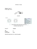
Страница 79: ...ICOM CI V Cable Minidin Jack 3 5 Cable Length 90 cm Jack 3 5 EzMaster Back Panel View Jack 3 5 MiniDin Tip 4 Ground 5 Cable Shield GND Tip and Ground need to be connected together...

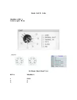
Страница 80: ...Radio KENWOOD Cable MiniDin 6 DIN 6 Cable Length 90 cm EzMaster Back Panel View DIN 6 MiniDin 6 1 GND 2 3 3 6 4 connected to 5 DIN 5 connected to 4 DIN...

Страница 81: ...Radio YAESU Cable MiniDin 6 DIN 6 Cable Length 90 cm EzMaster Back Panel View DIN 6 MiniDin 6 1 GND 2 4 3 5...

Страница 82: ...RTTY FSK AFSK ICOM Cable MiniDin 8 DIN 8 Cable Length 150 cm EzMaster Back Panel View DIN 8 MiniDin 8 1 1 2 2 3 3 2 4 4 6 2 5 5 7 2 8...

Страница 83: ...RTTY FSK AFSK FT1000 Mark V Cable MiniDin 8 DIN 4 Cable Length 150 cm EzMaster Back Panel View DIN 4 MiniDin8 1 1 4 2 3 3 4 4 2 7 4 8...

Страница 84: ...RTTY FSK AFSK Kenwood Cable MiniDin 8 DIN 13 Cable Length 150 cm EzMaster Back Panel View DIN 13 Minidin8 2 1 4 2 9 3 8 4 11 6 12 5 3 7 4 8...

Страница 85: ...RTTY FSK AFSK ORION Cable MiniDin 8 DIN 8 Cable Length 150 cm DIN 8 MiniDin 8 7 1 2 2 3 3 2 4 1 6 2 5 4 6 7 2 8...

Отзывы: