EZMaster
EZMaster
User’s Guide
Page 37 of 53
CW and PTT
Footswitch Operation
A footswitch can be connected to the PTT line on the back panel. A contact closure to ground activates the PTT.
CW and PTT signals from the PC
Most logging programs make the PTT and CW signals available on the LPT and/or USB/COM port. EZMaster supports PTT and CW
keying from either the LPT or the USB/Serial port. The Radio interface on the USB/Serial Port will still work even if the port has been
selected for PTT and CW keying.
The commands to select either the LPT or Serial port for the keying functions can be found in the relevant logging software manuals.
A red LED, on the front panel, indicates that the PTT is active, while a blinking green LED indicates that a CW or FSK keying is in
progress.
SO2R
Two-Radio Switching
The operator can choose to select RADIO A or B either manually or automatically under computer control. Manual selection is made
with the A/B key on the front panel keyboard or on the External keypad. Under computer control the active radio will follow the LPT
Parallel port Pin 14 status: a
high
status selects Radio A, while a
low
status selects Radio B.
The Mike, CW-key, RX Audio and PTT lines are switched, from one radio to the other, according to the same A/B signal.
RX Audio Switching
The received audio (headset output) from Radio A and from Radio B is fed into the two 6 pin minidin sockets, marked Speaker A and
Speaker B on the back panel of the unit.
The audio output is available on the 6.3mm stereo Headphones outlet located on the front panel.
The received audio switching can be controlled in two different ways, by pressing the Front Panel Keys, or, through the LPT Parallel port
control signals A/B (LPT pin 14), by the logging software that supports it.
−
Manual mode
In this mode the headphones are always connected to the active radio, selected from the front panel A/B key or by the A/B control
signals (LPT pin 14).
−
Split Mode
In this mode, the left ear of the headphones is connected to
Radio-A
and the right one to
Radio-B
. This mode is also supported
by those programs that work with the Radio A/B (LPT pin 14) and Stereo (LPT pin 9) signals.
−
Reverse Mode
Reverse the radio’s connection between the ears, to accommodate the operator needs.
−
AUTO
(fully Computer/Logging program Controlled)
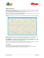
In AUTO mode EZMaster puts both ears on the “inactive” radio when a DVK or CW message is called for or sent from the logging
program. A user defined delay time can be added before switching ears to the inactive radio, allowing a short monitor of the
beginning of the transmission on the active radio.
Operation in ADVANCED mode
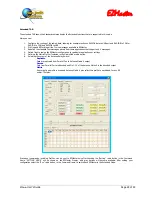
The ADVANCED mode can be set by a software program and allows the software to fully control EZMaster by sending all the relevant
commands via the USB line.
Whenever the operator needs to modify any software choice or setting, this can easily be done by a manual intervention via the front-
panel or the external keyboard.
Содержание EZMaster
Страница 52: ...EZMaster EZMaster User s Guide Page 52 of 53 Mainboard Printed Circuit Rev 4 00...
Страница 53: ...EZMaster EZMaster User s Guide Page 53 of 53 Take your Personal Notes here...
Страница 72: ...Microphone Cable ICOM EzMaster Back Panel View IcomMic EZMaster 1 4 7 5 5 2 6 3 Cable Lenght 90 cm...
Страница 73: ...Microphone Cable YAESU EzMaster Back Panel View YaesuMic EZMaster 8 4 7 5 6 2 5 3 Cable Lenght 90 cm...
Страница 74: ...Microphone Cable Kenwood EzMaster Back Panel View Kenwood Mic EZMaster 1 4 7 5 2 2 8 3 Cable Lenght 90 cm...
Страница 75: ...Microphone Cable Orion EzMaster Back Panel View Orion Mic EZMaster 2 4 1 5 3 2 4 3 Cable Lenght 90 cm...
Страница 78: ...CW Cable RCA Connector Jack 6 3 Cable Lenght 150 cm...
Страница 81: ...Radio YAESU Cable MiniDin 6 DIN 6 Cable Length 90 cm EzMaster Back Panel View DIN 6 MiniDin 6 1 GND 2 4 3 5...
Страница 85: ...RTTY FSK AFSK ORION Cable MiniDin 8 DIN 8 Cable Length 150 cm DIN 8 MiniDin 8 7 1 2 2 3 3 2 4 1 6 2 5 4 6 7 2 8...

