EZMaster
EZMaster
User’s Guide
Page 34 of 53
Advanced Mode Profiling
The Advanced Mode Profile allows the user to fully configure and define the status of each one of the 32 Antenna Relay Outputs.
These 32 output lines are grouped into 2 blocks:
−
16 lines for Antenna Matrix Port A
−
16 lines for Antenna Matrix Port B
Those lines are logically assigned as 16 lines for the external devices of Radio A, and 16 lines for the Radio B, on two different DB25
connectors, each one including also the last 6 lines of the other port, so in this way the user is free to configure them all for satisfying
his personal needs, regardless the connector involved.
The idea behind profiles is that, for each band, for each radio, either in RX or in TX mode, each one of the 32 ports can be configured
to enable or disable (ON/OFF) the corresponding line.
In particular, one of the big differences between EZMaster and other standard Parallel Antenna Matrix Output is that you can directly
select any output without the need of any additional external wired diode for a matrix antenna/filter switch configuration.
The data are available separately, simultaneously, on both ports, so the antennas that are connected to Port B, normally associated to
Radio B, stay connected also when Radio A is selected! In this way the user can share the antennas, can select the filters for both
Output and Radio separately.
The last feature, or the cherry upon the cake, is that each configuration can be enabled for both Radio A and Radio B, either in RX and
in TX mode, thus allowing to select an antenna system while in RX and another one while in TX, like typically you receive with a
Beverage and transmit with a Vertical, or you transmit with a power splitter to a stack beaming in two direction and receive only in one
direction. Moreover you can even define a sequence of receiving antennas to cover the whole 360°.
The device is so flexible that the software developer or the user himself can just rely on his own fantasy to look for a new application.
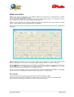
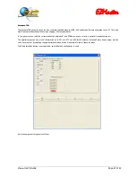
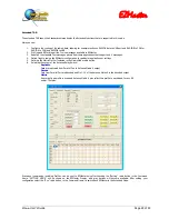
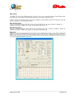
Here some snapshot follow, representing in brief how to configure the Antenna Matrix Port output.
ANTENNA MATRIX
PORT “A” RX
Configuration
ANTENNA MATRIX
PORT “A” TX
Configuration
Содержание EZMaster
Страница 52: ...EZMaster EZMaster User s Guide Page 52 of 53 Mainboard Printed Circuit Rev 4 00...
Страница 53: ...EZMaster EZMaster User s Guide Page 53 of 53 Take your Personal Notes here...
Страница 72: ...Microphone Cable ICOM EzMaster Back Panel View IcomMic EZMaster 1 4 7 5 5 2 6 3 Cable Lenght 90 cm...
Страница 73: ...Microphone Cable YAESU EzMaster Back Panel View YaesuMic EZMaster 8 4 7 5 6 2 5 3 Cable Lenght 90 cm...
Страница 74: ...Microphone Cable Kenwood EzMaster Back Panel View Kenwood Mic EZMaster 1 4 7 5 2 2 8 3 Cable Lenght 90 cm...
Страница 75: ...Microphone Cable Orion EzMaster Back Panel View Orion Mic EZMaster 2 4 1 5 3 2 4 3 Cable Lenght 90 cm...
Страница 78: ...CW Cable RCA Connector Jack 6 3 Cable Lenght 150 cm...
Страница 81: ...Radio YAESU Cable MiniDin 6 DIN 6 Cable Length 90 cm EzMaster Back Panel View DIN 6 MiniDin 6 1 GND 2 4 3 5...
Страница 85: ...RTTY FSK AFSK ORION Cable MiniDin 8 DIN 8 Cable Length 150 cm DIN 8 MiniDin 8 7 1 2 2 3 3 2 4 1 6 2 5 4 6 7 2 8...


