


12 of 96
Installation - 3624 ProBrix Plus
Operator Manual
ORBISPHERE
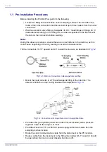
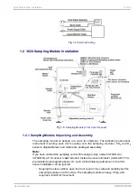
• Open the sampling module and check for shipment damages inside the sampling
module. Retighten all fittings in the sampling module.
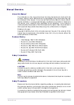
• Attach the four adjustable feet to the bottom of the sampling module (see
).
Do not tighten the locking nut yet.
• Place the CO
2
sensor and the O
2
sensor in their respective flow chamber
mountings inside the sampling module (see
), using their collar to secure
each sensor into place.
• Connect the cables with 10-pin LEMO connectors to the CO
2
sensor and the O
2
sensor. The CO
2
sensor cable connects to the purge backup unit; the O
2
sensor
cable connects to the Brix/Diet sensor controller.
CAUTION:
Take care to connect the O
2
sensor to the correct cable, as it can be damaged if
plugged into the CO
2
sensor cable.
• Connect the temperature sensor to the CO
2
sensor's temperature adapter using
the cable with the 4-pin LEMO connector.
• Connect the CO
2
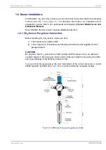
sensor's purge gas tubing from the purge gas regulator, and re-
tighten all purge gas fittings (see also
Sensor Purge Gas Connection” on
• Install the 3mm (inside diameter) purge gas exit tube into the CO
2
sensor
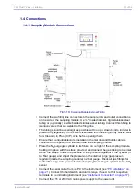
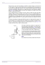
• If you have also taken delivery of the sample filter, install this on the sample inlet
tube using standard Swagelok connections (see also
for additional information).
• Reposition the ProBrix Plus to its final location.
• Make sure the sampling module vents (on both the left and right sides) are
sufficiently unobstructed to allow airflow to the pump. The pump must have
adequate airflow to prevent it from overheating.
CAUTION:
Prevent water from being sprayed directly into these vents.
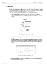
• Secure the sampling module feet to the floor if necessary. The feet have holes that
can be used to bolt the unit to the ground.
• Adjust the four feet to level the unit. To test, place a level on top of the Brix/Diet
sensor inside the sampling module. It should be level (or tilted slightly
counterclockwise, just 1-2° to the left as you face the unit) to avoid liquid collecting
inside its U-tube densitometer.
Fig 1-6:
Adjustable Feet Locking Nut
Содержание ORBISPHERE 3624
Страница 1: ...Operator Manual ORBISPHERE 3624 Revision F 03 10 2008 ...
Страница 2: ......
Страница 14: ...8 of 96 Manual Overview 3624 ProBrix Plus Operator Manual ORBISPHERE ...
Страница 32: ...26 of 96 Installation 3624 ProBrix Plus Operator Manual ORBISPHERE ...
Страница 60: ...54 of 96 PC Program Setup 3624 ProBrix Plus Operator Manual ORBISPHERE ...
Страница 68: ...62 of 96 Calibrations 3624 ProBrix Plus Operator Manual ORBISPHERE ...
Страница 82: ...76 of 96 Accessories and Attachments 3624 ProBrix Plus Operator Manual ORBISPHERE ...
Страница 98: ...92 of 96 Glossary 3624 ProBrix Plus Operator Manual ORBISPHERE ...
Страница 101: ...3624 ProBrix Plus User Notes 95 of 96 Operator Manual ORBISPHERE User Notes ...
Страница 102: ......


