


16 of 96
Installation - 3624 ProBrix Plus
Operator Manual
ORBISPHERE
1.4.2 Indicating Instrument Electrical Connections
WARNING
The installation of a 3624 instrument should only be performed by personnel specialized
and authorized to work on electrical installations, in accordance with relevant European
and/or national regulations. In accordance with standard EN 61010-1, it must be
possible to disconnect the power supply of a 3624 instrument in its immediate vicinity.
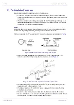
While the instrument's electronics are well shielded, it is still advisable to locate the
instrument as far away as possible from any source of electromagnetic perturbation.
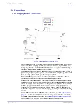
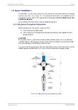
Connections from the instrument to the Brix/Diet, CO
2
, and O
2
sensors, and for
instrument to sampling module communication, use three snap-in LEMO receptacles on
the bottom of the instrument housing. The instrument's AC power connection uses a
screw-in Binder connector.
• Typically, these connectors are concealed by the stainless steel neck used to
mount the instrument to the sampling module (see illustrations in
) and are not seen by the operator.
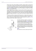
• On a wall-mount instrument, extension cables must be provided to enable
connections to the LEMO connectors and the Binder connector (see your Hach
Ultra Service Representative for details).
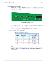
Connections for serial data, recorder output, hold switch, and alarm relays use watertight
cable glands at the bottom of the instrument housing. The user must wire his cables to a
terminal block inside the instrument.
WARNING
Make sure to disconnect the power supply before opening the instrument.
To open the front panel of the instrument, make sure the power supply is unplugged, and
use the key provided to unlock the door. Carefully pull the door back, to expose the
instrument electronics inside. The terminal block connectors are on a printed circuit
board, part number 1126A (this number is printed on the lower edge of the card), located
at the rear of the instrument within the instrument housing (see
).
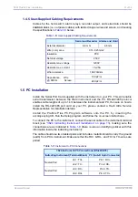
Instructions for wiring the cables through the cable glands are provided in
Wiring Instructions” on page 20
. Requirements for these user-supplied cables are
provided in
“User-Supplied Cabling Requirements” on page 21
(see also
for additional PC cable wiring information).
Содержание ORBISPHERE 3624
Страница 1: ...Operator Manual ORBISPHERE 3624 Revision F 03 10 2008 ...
Страница 2: ......
Страница 14: ...8 of 96 Manual Overview 3624 ProBrix Plus Operator Manual ORBISPHERE ...
Страница 32: ...26 of 96 Installation 3624 ProBrix Plus Operator Manual ORBISPHERE ...
Страница 60: ...54 of 96 PC Program Setup 3624 ProBrix Plus Operator Manual ORBISPHERE ...
Страница 68: ...62 of 96 Calibrations 3624 ProBrix Plus Operator Manual ORBISPHERE ...
Страница 82: ...76 of 96 Accessories and Attachments 3624 ProBrix Plus Operator Manual ORBISPHERE ...
Страница 98: ...92 of 96 Glossary 3624 ProBrix Plus Operator Manual ORBISPHERE ...
Страница 101: ...3624 ProBrix Plus User Notes 95 of 96 Operator Manual ORBISPHERE User Notes ...
Страница 102: ......


