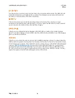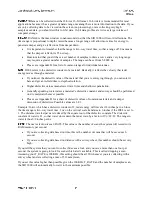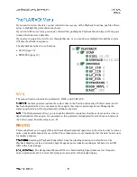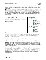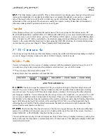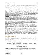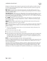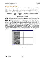
LP_IIR
HP_IIR
LP_FIR
HP_FIR
STACKING
BGR_REMOVAL
The first four are frequency filters and the values are all expressed in
MHz.
The two types of filters that we are using are the Finite Impulse Response (FIR), and Infinite Impulse
Response (IIR). We are using these to downplay external interference, and thus clean up the signal. The
FIR filter does this without altering the phase of the signal. For some antennas we also use a very low IIR
filter to clean certain characteristics of that antenna’s signal. These filters are antenna-specific and are set
automatically when you recall the proper setup for your antenna.
FIR filters should not be used with 4096 or 8192 samples per scan.
LP stands for low-pass, which means that any frequency lower than the one entered here will be
allowed to pass by and be recorded by the system.
HP stands for high pass, which means that any frequency higher than the one entered here will be
allowed to pass by and be recorded by the system.
By setting these at different ends of the antenna’s bandwidth, you are determining the range of
frequencies that the antenna is filtering out.
The default values will be adequate in almost all situations.
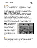
After the frequency filters, the next choice is Stacking. Stacking is a high-frequency noise
reduction technique. It is an IIR filter which operates in the horizontal direction. Each new scan has a 1/n
influence in the data, so this filter has a tendency to smooth high frequency targets and accentuate low
frequency horizontal features, such as layers. As the number of scans you stack (n) increases, the
influence of each new scan drops. If you put in a very high number, you will filter out high frequency
targets in your data. This might lead to missing real targets in your data.
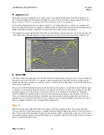
High frequency noise generally has a ‘snowy’ appearance.
The larger the number you put in here, the smoother the data will be. It is possible to over smooth
and ‘smudge’ out real data.
A larger number also means that the system is performing a great deal of extra calculations and
data collection speed will then be reduced.
The Background Removal filter is a horizontal high pass (remove low frequency
noise) operation meant to remove flat-lying noise associated with antenna ringing.
The input number here is scans, so in order to use this filter, find the length in scans of the feature that
you want to remove and put that number into the system. Features of this size or larger will be removed
from the data.
Also please note that this filter will remove your direct coupling, making positive identification of
Time Zero difficult. To preserve data integrity it is best to collect data without this filter and then
apply it in playback or post-processing if needed.

