Grizzly G0699 Скачать руководство пользователя страница 96

-94-

Model G0699 (Mfd. Since 5/15)

BUY PARTS ONLINE AT GRIZZLY.COM!

Scan QR code to visit our Parts Store.
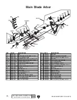
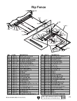
Crosscut Fence

901

902

903

904

905

905A

909A

906

907

935 936

923

908

909V2

942

940

939

941

910V2

911

912

913

914

915

916V2

917

937

938

918

919

920V2

921

924

925

926

927

929V2

901

928

943

REF PART #

DESCRIPTION

REF PART #

DESCRIPTION

901

P06990901

T-NUT M8-1.25

919

P06990919

T-NUT M8-1.25

902

P06990902

STOP BRACKET

920V2 P06990920V2 POLYURETHANE FENCE END PIECE V2.04.12

903

P06990903

KNOB BOLT M8-1.25 X 40

921

P06990921

PHLP HD SCR M4-.7 X 10

904

P06990904

FLIP STOP PIVOT SHAFT

923

P06990923

FIBER FLAT WASHER

905A

P06990905A

FLIP STOP ASSEMBLY

924

P06990924

CAP SCREW M8-1.25 X 35

905

P06990905

FLIP STOP

925

P06990925

LOCK WASHER 8MM

906

P06990906

SET SCREW M8-1.25 X 10

926

P06990926

T-BLOCK

907

P06990907

LOCK NUT M10-1.5

927

P06990927

T-NUT M8-1.25

908

P06990908

EXTENSION CONNECTOR

928

P06990928

SET SCREW M6-1 X 6

909A

P06990909A

EXTENSION FENCE ASSEMBLY

929V2 P06990929V2 T-BOLT M8-1.25 X 35 V2.05.12

909V2 P06990909V2 EXTENSION FENCE V2.04.12

935

P06990935

SLEEVE

910V2 P06990910V2 EXTENSION FENCE END PLATE V2.04.12

936

P06990936

CAP SCREW M3-.5 X 12

911

P06990911

TAP SCREW M4 X 10

937

P06990937

FENDER WASHER 8MM

912

P06990912

BUTTON HD CAP SCR M8-1.25 X 16

938

P06990938

FENCE LOCK HANDLE

913

P06990913

LOCK WASHER 8MM

939

P06990939

FENCE SCALE 0"-78"

914

P06990914

SUPPORT PLATE

940

P06990940

FENCE SCALE 67"-135"

915

P06990915

KNOB BOLT M8-1.25 X 25

941

P06990941

T-SLOT NUT M5-.8 (THIN)

916V2 P06990916V2 CROSSCUT FENCE V2.04.12

942

P06990942

CAP SCREW M5-.8 X 6

917

P06990917

PIVOT SHAFT

943

P06990943

SET SCREW M5-.8 X 5

918

P06990918

FIBER FLAT WASHER 10MM

Содержание G0699

Страница 1: ...models manufactured since 5 15 COPYRIGHT JUNE 2010 BY GRIZZLY INDUSTRIAL INC REVISED SEPTEMBER 2018 MN WARNING NO PORTION OF THIS MANUAL MAY BE REPRODUCED IN ANY SHAPE OR FORM WITHOUT THE WRITTEN APP...

Страница 2: ...g grinding tool integrity and the usage of personal protective equipment The manufacturer will not be held liable for injury or property damage from negligence improper training machine modifications...

Страница 3: ...Scoring Blade 52 Rip Cutting 54 Crosscutting 56 Miter Cutting 58 SECTION 5 ACCESSORIES 59 SECTION 6 SHOP MADE SAFETY ACCESSORIES 61 Push Sticks 61 Push Blocks 63 SECTION 7 MAINTENANCE 67 Schedule 67...

Страница 4: ...machine leaves you confused or unsure about something check our website for an updated version We post current manuals and manual updates for free on our web site at www grizzly com Alternatively you...

Страница 5: ...g Extension Wing End Shoe Blade Tilt Handwheel Scale STOP Button For Your Own Safety Read Instruction Manual Before Operating Saw a Wear eye protection b Use saw blade guard and riving knife for every...

Страница 6: ...Machine Weight 1314 lbs Length x Width x Height 45 x 82 x 44 in Must Ship Upright Yes Carton 2 Type Wood Crate Content Sliding Table Weight 346 lbs Length x Width x Height 19 x 133 x 12 in Must Ship U...

Страница 7: ...0 Deg 3 5 16 in Max Depth of Cut At 45 Deg 2 3 8 in Rip Fence Max Cut Width 49 3 4 in Sliding Table w Crosscut Fence Max Cut Width 126 in Sliding Table w Crosscut Fence Max Cut Length 126 in Miter Fen...

Страница 8: ...3 4777 Fax 800 438 5901 SLIDING TABLE SAW CAPACITIES Ripping Width Miter Cut 90 push cut Miter Cut 45 Miter Cut 45 push cut Cross Cut fence not extended Miter Cut 45 push cut fence not extended Miter...

Страница 9: ...oof DANGEROUS ENVIRONMENTS Do not use machinery in areas that are wet cluttered or have poor lighting Operating machinery in these areas greatly increases the risk of accidents and injury MENTAL ALERT...

Страница 10: ...moving parts or flying debris Make sure they are properly installed undamaged and working correctly BEFORE operating machine FORCING MACHINERY Do not force machine It will do the job safer and better...

Страница 11: ...rt saw with workpiece touching blade Allow blade to reach full speed before cutting Only feed workpiece against direc tion of main blade rotation Always use some type of guide to feed workpiece in a s...

Страница 12: ...kickback and reduces your risk of injury if it does occur Always keep blade guard installed and in good working order Feed cuts through to completion Any time you stop feeding a workpiece in the middl...

Страница 13: ...piece back toward the operator with what sounds like a horrible explosion The danger comes from flying stock striking the operator or bystanders The operator s hands may also be pulled into the blade...

Страница 14: ...ion and make sure it is connected to a power supply circuit that meets the specified circuit requirements Circuit Requirements for 440V This machine can be converted to operate on a 440V power supply...

Страница 15: ...Gauge Size 8 AWG Maximum Length Shorter is Better 50 ft Grounding Instructions This machine MUST be grounded In the event of certain malfunctions or breakdowns grounding reduces the risk of electric...

Страница 16: ...led on the electrical panel see Figure 5 and refer to Electrical Cabinet Wiring Diagram on Page 80 4 Disconnect and remove both overload relays then replace them with the relays included in the 440V c...

Страница 17: ...the polarity of the power source legs wiring machinery to 3 phase power may require trial and error Correcting phase polarity is simply a matter of reversing the positions where two of the incoming p...

Страница 18: ...the controls and opera tions before starting the machine Wear safety glasses during the entire setup process HEAVY LIFT Straining or crushing injury may occur from improperly lifting machine or some...

Страница 19: ...upport Arm 1 V Dust Hose 3 1 W Dust Port Connection 3 1 X Tool Box Not Shown 1 Scoring Arbor Wrench 1 Combo Wrench 17 19mm 1 Wrench 30mm 1 T Handle Wrench 8mm 1 Figure 8 Crate 1 inventory NOTICE If yo...

Страница 20: ...nder Washer 8mm 1 Knobs M8 1 25 2 Pivot Stud M8 1 25 x 15 1 Fiber Flat Washers 8mm 2 T Nuts M8 1 25 3 Knob M8 1 25 x 25 w Nylon Tip 1 Knob M8 1 25 x 50 1 Stop Block 1 Cap Screw M8 1 25 x 35 1 Lock Was...

Страница 21: ...Model G0699 Mfd Since 5 15 19 5mm Hardware Recognition Chart...

Страница 22: ...ps for removing rust preventative 1 Put on safety glasses 2 Coat the rust preventative with a liberal amount of cleaner degreaser then let it soak for 5 10 minutes 3 Wipe off the surfaces If your clea...

Страница 23: ...hysical Environment The physical environment where the machine is operated is important for safe operation and lon gevity of machine components For best results operate this machine in a dry environme...

Страница 24: ...de arbors exposed Scoring Blade T Handle Wrench Main Blade Arbor HEAVY LIFT Straining or crushing injury may occur from improperly lifting machine or some of its parts To reduce this risk get help fro...

Страница 25: ...safely secure the blade Figure 15 Installing main blade 5 Install and align riving knife refer to Riving Knife Alignment beginning on Page 48 for detailed information Figure 14 Main blade arbor nut a...

Страница 26: ...in Step 9 Slide the sliding table base out of the way to install the two larger cap screws shown in Figure 19 9 Remove the four cap screws threaded into the end of the sliding table assembly the cap s...

Страница 27: ...ng and kicking back 13 Move the sliding table all the way back 14 Tilt the main saw blade to 0 and raise it all the way up 15 Use the felt tip pen to mark the right blade edge that is even with the ta...

Страница 28: ...e 23 Sliding table parallel adjustment bolt 1 of 2 Parallel Adjustment Bolt Jam Nut 1 of 2 Figure 24 Location of the forward sliding table T bolt from the rear of the frame 23 Make sure the sliding ta...

Страница 29: ...ing cap screws on both wings see Figures 27 28 Make sure the set screws do not stick out from the wing mating surface which would interfere with the leveling process in the next step 28 Place the stra...

Страница 30: ...e fully tightened in a later step Figure 30 Rip fence scale attached Rip Fence Scale Figure 32 Rip fence body assembly installed Micro Adjust Lock Knob Fence Clamp Handle Fence Lock Handle Figure 31 R...

Страница 31: ...elow the table surface Note This will keep the scoring blade from interfering with the rip fence alignment pro cess in the next steps Figure 35 Lowering the scoring blade Figure 36 Rip fence against t...

Страница 32: ...n in Figure 37 Loosen the acorn nut adjust the roller until it extends slightly beyond the body then re tighten the acorn nut If the rear end of the fence body rests on the table adjust the height of...

Страница 33: ...ep is to adjust the scor ing blade vertical and horizontal positions so that the scoring kerf is the same width as the main saw blade kerf This procedure requires placing the straightedge on both side...

Страница 34: ...dle installed T Nut Plate Lock Handle 49 With the help of another person place the crosscut table on the swing arm pivot pin as shown in Figure 44 then slide the T plate into the sliding table T slot...

Страница 35: ...ition then hand tighten the M8 1 25 x 10 pivot stud with the 8mm fiber flat washer into the T nut as shown in Figure 47 53 Turn the crosscut fence over insert the pivot stud in its placement hole see...

Страница 36: ...uts from pre installed arm support studs see Figure 51 and install support arm base onto arm support studs as shown in Figure 52 60 Adjust arm leveling bolt until arm support base is parallel with flo...

Страница 37: ...stal x 4 Figure 53 Securing arm support base Bracket Arm Leveling Bolt M20 2 5 Hex Nut w Fender Washer 1 of 2 Jam Nut 64 Insert upper support arm into top of arm support pedestal as shown in Figure 55...

Страница 38: ...sure both blade rollers are centered over blade and if necessary loosen hex bolt from Step 65 on Page 35 slide upper support arm until rollers are centered over blade then re tighten hex bolt to secu...

Страница 39: ...el with table If necessary loosen M20 2 5 hex nuts from Step 62 repeat Steps 60 61 until rollers are parallel with table then re tighten hex nuts 72 Attach dust port to upper support arm using 2 M6 1...

Страница 40: ...between the dust col lector and the machine 3 number of branches or wyes and 4 amount of other open lines throughout the system Explaining how to cal culate these variables is beyond the scope of thi...

Страница 41: ...box see Figure 66 Figure 67 Incoming power connections Hot Connections Ground Connection 3 Make sure there is enough power cord inside the junction box to make the connections with the same amount of...

Страница 42: ...e test run consists of verifying the following 1 The motors power up and run correctly 2 the safety features of the Emergency Stop button and blade cover switch work correctly and 3 the main blade tur...

Страница 43: ...Polarity on Page 15 to correct this condition Correct Not Correct Viewed Facing Blade From Front Figure 70 Correct and incorrect rotation directions for the main blade 11 While staying safely away fro...

Страница 44: ...least verify the following adjustments to ensure the best possible results from your new machine Step by step instructions for these adjustments can be found on the referenced page for each item Facto...

Страница 45: ...erator does the following 1 Examines workpiece to make sure it is suit able for cutting 2 Adjusts blade tilt if necessary to correct angle of desired cut 3 Adjusts blade height approximately 1 4 highe...

Страница 46: ...ys aligned with the main blade before cutting Always keep the blade guard properly installed Carefully plan each cutting operation to avoid injuries When you release the sliding table lock make sure t...

Страница 47: ...rotated to the right the lock releases and allows the table to slide freely Rip Fence Clamp Lever Secures the rip fence to the rip fence body Rip Fence Lock Lever Clamps the rip fence assembly in pla...

Страница 48: ...moisture content over 20 causes unneces sary wear on the blades increases the risk of kickback and yields poor results Excessive Warping Workpieces with exces sive cupping bowing or twisting are dang...

Страница 49: ...operly maintains blade after the workpiece exits Lock Handle Guard Loosen the hex bolt securing the guard arm see Figure 79 and adjust the guard so the distance between the blade and both side covers...

Страница 50: ...knife must be posi tioned within 3 8mm of the blade as shown in Figure 84 The riving knife see Figure 81 is a metal plate that prevents the workpiece from pinching the backside of the blade and causi...

Страница 51: ...l with the blade refer to Riving Knife Mounting Block on Page 77 The riving knife included with this machine is 0 10 2 5mm thick and is only designed for 12 diam eter blades When choosing a main blade...

Страница 52: ...lternate top bevel and raker tooth profile Teeth are arranged in groups Gullets are small and shallow similar to a cross cut blade then large and deep similar to a ripping blade Alternate Top Bevel an...

Страница 53: ...he blade arbor from rotating during the next step Figure 91 Loosening the main blade arbor nut 6 While holding the T handle wrench with one hand rotate the arbor nut clockwise until you can remove it...

Страница 54: ...the blade all the way up 3 Raise blade guard up and move it away from blade 4 Move the sliding table all the way forward to expose the blade cover lock it in place then open the blade cover 5 Place th...

Страница 55: ...the red blade cover lock it in place then open the blade cover Vertical Adjustment Insert the T handle wrench into the left hole shown in Figure 96 engage it with the adjustment bolt under the table...

Страница 56: ...rosscut Fence to Blade on Page 76 3 Loosen the crosscut fence pivot stud under the crosscut fence insert it into its hole in the crosscut table then rotate the fence against the 90 stop bolt Note The...

Страница 57: ...t is either across the full width of the table or optionally even with the center of the main saw blade as shown in Figure 101 then re tighten the clamp handle Note The rip fence position shown below...

Страница 58: ...r position for smaller panels When setup properly this table saw also has the capability of crosscutting workpieces while using the rip fence as a cut off gauge as shown in Figure 105 Figure 105 Cross...

Страница 59: ...ount the crosscut fence in the rear position as indi cated in Figure 106 on the previous page Then load the workpiece so your setup looks similar to Figure 104 on the previous page Crosscutting Using...

Страница 60: ...hown in Figure 109 Figure 110 Crosscut fence positioned for miter cuts from 90 to 135 For miter cuts from 90 to 135 insert the fence pivot stud into the forward hole and angle the fence to the rear as...

Страница 61: ...saw will make repetitive cuts much easier and safer Can be installed on nearly any table saw Easy to adjust wherever needed including out of the way when not needed A must for any shop Installing una...

Страница 62: ...lector performance Casters mounted to the steel drum also make disposal of the larger chips and dust as easy as it gets Figure 114 Model G0440 Cyclone Dust Collector Figure 116 Superbar and Master Pla...

Страница 63: ...push stick is included with your table saw To make additional push sticks refer to the template in Figure 118 for construction details 90 Cut here to push 1 4 stock Cut here to push 1 2 stock Notch fo...

Страница 64: ...he workpiece against or behind the blade see Push Stick Prohibition Zone in Figure 119 Otherwise pressure from the push stick will increase the risk of kickback Push sticks should be made of plywood o...

Страница 65: ...ing a Push Block A push block can be used in place of or in addi tion to a push stick for feeding workpieces into the blade Due to their design push blocks allow the operator to apply firm downward pr...

Страница 66: ...h Block for an Auxiliary Fence 1 Cut a piece of 1 2 thick plywood 6 by 391 2 and cut a piece of 3 4 thick hardwood 3 by 391 2 as shown in Figure 124 Using a Push Block 1 Place the lip of the push bloc...

Страница 67: ...the 6 and 3 wide boards with eight 6 x 1 4 wood screws through the holes you drilled in Step 2 the fence should look like the one shown in Figure 126 4 Cut a piece of plywood 15 long and 51 4 wide fo...

Страница 68: ...ng a push stick for side sup port As the workpiece nears the end of the cut place the push block on the auxiliary fence with the lip directly behind the workpiece then release the push stick just befo...

Страница 69: ...8 Lubricate tilt and elevation leadscrews Page 69 Schedule Cleaning the Model G0699 is relatively easy Vacuum excess wood chips and sawdust and wipe off the remaining dust with a dry cloth If any resi...

Страница 70: ...the cabinet see Figure 132 Important The position of the four upper lock nuts were set at the factory so that the cast iron table is square with the saw blade from side to side and back to front DO NO...

Страница 71: ...d shop rags then apply a thin coat of light machine oil with a shop rag Move the sliding table through its full range of movement several times to evenly distribute the oil Replacing Main Table Replac...

Страница 72: ...e weak breaker check wiring at machine 7 Test for power on all legs and contactor operation Replace unit if faulty 8 Check for broken wires or disconnected corroded connections and repair replace as n...

Страница 73: ...r kicks back 1 Sliding table or rip fence is not parallel to blade 2 Riving knife is not aligned with the blade 3 Blade is warped or damaged 1 Make sliding table or rip fence parallel to the blade Pag...

Страница 74: ...etailed instructions Note Replace the main motor V belts as a matched set so that they will wear evenly Main Motor V Belts 1 DISCONNECT SAW FROM POWER 2 Loosen the three mounting hex bolts shown in Fi...

Страница 75: ...1 45 Square 1 To calibrate the tilt stop nuts 1 DISCONNECT SAW FROM POWER 2 Raise the main blade all the way up and tilt it all the way toward the 0 mark until it stops This moves the leadscrew clamp...

Страница 76: ...aw blade to 0 and raise it all the way up 4 Use the felt tip pen to make a mark on the right blade edge that is even with the table 5 Use the adjustable square to measure the distance from the sliding...

Страница 77: ...remov ing the access panels on both sides of the frame and the middle hex nut through the 5 dust port gap in the cabinet side 9 Make sure the sliding table is up against the adjustment bolts then repe...

Страница 78: ...in Figure 146 Test Piece 1 2 3 4 Figure 146 Crosscut fence adjustment test piece 3 Move the crosscut fence stop block against one of the 90 stop bolts then use the fence to cut 1 2 off each side of th...

Страница 79: ...knife to mounting block and remove riving knife 6 Adjust each pair of set screws that controls the direction required to move mounting block so riving knife can be aligned with blade Make sure to move...

Страница 80: ...h Loosen acorn nut see Figure 148 adjust wheel position retight en acorn nut and place rip fence base back on table Parallelism To Blade Tool Needed Qty Wrench 19mm 1 To adjust the rip fence parallel...

Страница 81: ...e check all wires dis connected or connected during any wiring task to ensure tight connections CIRCUIT REQUIREMENTS You MUST follow the requirements at the beginning of this manual when connecting yo...

Страница 82: ...2 Amp 250V Fuse W V U W V U W1 V1 U1 W1 V1 U1 W V U W1 V1 U1 Contactor SDE MA 30 220V Contactor SDE MA 09 220V 220V Overload Relay SDE RA 30 220V Overload Relay SDE RA 20 Ground Ground E E C D 220V 4...

Страница 83: ...coring Main 12 11 24 23 Control Panel Viewed From Behind STOP Button Blade Guard Safety Swtich 4 7 5 1 1 2 3 4 R S T HOT HOT HOT Ground 220V 3 Phase NEMA L15 30 As Recommended Power Connection Junctio...

Страница 84: ...2 8 1 7 Ground 9 3 6 4 5 2 8 1 7 Ground 1 7 8 2 3 9 6 4 5 12 10 11 W1 V1 U1 Ground 1 7 8 2 3 9 4 5 6 12 10 11 W1 V1 U1 Additional 440V Conversion Steps Required 220V Scoring Motor 440V Scoring Motor...

Страница 85: ...EAD ELECTRICAL SAFETY ON PAGE 79 Figure 150 Electrical panel wiring Figure 151 Control panel wiring Figure 152 Main motor wiring Figure 153 Scoring motor wiring Electrical Component Photographs Figure...

Страница 86: ...t our Parts Store Cabinet Body SECTION 10 PARTS 1 2 3 8 9 16 17 18 19 20 28 29 30 31 32 33 34 35 36 40 41 42 43 44 45 46 47 48 49 50 51 52 53 54 61 93 96 94 65 66 67 92 95 91 90 68 69 70 71 72 73 74 7...

Страница 87: ...UTTON HD CAP SCR M6 1 X 10 75 P06990075 SET SCREW M5 8 X 10 31 P06990031 BLADE TILT TRUNNION 76 P06990076 POINTER BRACKET 32 P06990032 FLAT WASHER 10MM 77 P06990077 CAP SCREW M6 1 X 12 33 P06990033 LO...

Страница 88: ...M10 1 5 X 20 108 P06990108 LOCK WASHER 10MM 102 P06990102 HEX NUT M10 1 5 109 P06990109 BUTTON HD CAP SCR M6 1 X 12 103 P06990103 LEFT EXTENSION WING 110 P06990110 SAW TABLE ANGLE INSERT 104 P06990104...

Страница 89: ...SCREW M5 8 X 12 240 P06990240 LOCK WASHER 12MM 211 P06990211 LOCK WASHER 5MM 241V2 P06990241V2 HEX BOLT M12 1 75 X 35 V2 06 15 212 P06990212 CAP SCREW M8 1 25 X 12 242 P06990242 KEY 8 X 7 X 40 216 P06...

Страница 90: ...ER 306V2 P06990306V2 RIVING KNIFE V2 10 16 327 P06990327 LOCK WASHER 8MM 307 P06990307 FRONT RIVING KNIFE BRACKET 328 P06990328 CAP SCREW M8 1 25 X 20 308 P06990308 KEY 5 X 5 X 20 329V2 P06990329V2 AR...

Страница 91: ...430 P06990430 LOCK WASHER 6MM 407 P06990407 BEARING WASHER 431 P06990431 ELEVATION LEADSCREW CLAMP 408V2 P06990408V2 BALL BEARING 6902 2RS V2 11 13 432 P06990432 CAP SCREW M8 1 25 X 60 409 P06990409...

Страница 92: ...INT RETAINING RING 35MM 526 2 P06990526 2 SCORING MOTOR FAN 507 P06990507 ARBOR HOUSING 526 3 P06990526 3 SCORING MOTOR JUNCTION BOX 508 P06990508 FLAT WASHER 6MM 527 P06990527 HEX NUT M10 1 5 509 P06...

Страница 93: ...AL ADJUSTMENT SHAFT 612 P06990612 VERTICAL ADJUSTMENT SHAFT 604 P06990604 ECCENTRIC SHAFT 613 P06990613 SET SCREW M6 1 X 25 605 P06990605 LOCK NUT M6 1 614 P06990614 HEX NUT M6 1 606 P06990606 BELLEVI...

Страница 94: ...MAGNET HOLDER 724 P06990724 FLAT WASHER 6MM 707 P06990707 SLIDING TUBE 725 P06990725 CAP SCREW M6 1 X 20 708 P06990708 HEX BOLT M8 1 25 X 20 726 P06990726 FLAT WASHER 20MM 709 P06990709 HEX NUT M8 1 2...

Страница 95: ...3 8 833 P06990833 KNOB BOLT M8 1 25 X 50 813 P06990813 BRACE END PLUG 834 P06990834 INT RETAINING RING 32MM 814 P06990814 CROSSCUT TABLE BRACE 835 P06990835 PIVOT BLOCK 815 P06990815 LOCK T BAR 836 P...

Страница 96: ...MM 906 P06990906 SET SCREW M8 1 25 X 10 926 P06990926 T BLOCK 907 P06990907 LOCK NUT M10 1 5 927 P06990927 T NUT M8 1 25 908 P06990908 EXTENSION CONNECTOR 928 P06990928 SET SCREW M6 1 X 6 909A P069909...

Страница 97: ...1 1009 P06991009 LOCK DOWN HANDLE 1047 P06991047 LOCK NUT M8 1 25 1013 P06991013 FLAT HD SCR M6 1 X 16 1048 P06991048 HEX NUT M8 1 25 1017 P06991017 CLAMP PLATE 1049 P06991049 ROLLER 1018 P06991018 R...

Страница 98: ...V2 05 11 1129V2 P06991129V2 BLOCK PLATE V2 05 11 1155 P06991155 FLAT HD SCR M6 1 X 30 1130V2 P06991130V2 BLOCK PLATE V2 05 11 1156 P06991156 BUTTON HD CAP SCR M5 8 X 10 1131V2 P06991131V2 SLIDING TABL...

Страница 99: ...24 13 1224 14 1224 15 1224 16 1225 1226 1227 1228 1229 1230 1231 1232 1233 1234 1235 1236 1237 1238 1239 1240 1241 1242 1243 1246 1247 1248 1249 1250 1251 1251 1252 1253 1254 1254 1 1254 2 1254 3 1254...

Страница 100: ...CREW M6 1 X 25 1255 8 P06991255 8 ROLLER SHAFT 1224 16 P06991224 16 DUST HOOD MOUNTING PLATE 1256 P06991256 BLADE GUARD ASSY NARROW 1225 P06991225 DUST PORT 3 1256 1 P06991256 1 BLADE GUARD BODY 1226...

Страница 101: ...DESCRIPTION 1301 P06991301 ELECTRICAL CABINET BACK PLATE 1307 P06991307 FUSE 2A 1302 P06991302 TERMINAL BAR 3 POST 1308 P06991308 OL RELAY SDE RA 30 18 26A 1303 P06991303 TERMINAL BAR 6 POST 1309 P069...

Страница 102: ...7V2 1408V2 REF PART DESCRIPTION REF PART DESCRIPTION 1401 P06991401 TOOL BOX 1405 P06991405 T HANDLE WRENCH 8MM 1402V2 P06991402V2 SCORING ARBOR WRENCH V2 04 12 1406 P06991406 PUSH STICK 1403 P0699140...

Страница 103: ...1509 1510 1511 1512 1513 Safety labels warn about machine hazards and ways to prevent injury The owner of this machine MUST maintain the original location and readability of the labels on the machine...

Страница 104: ...CONTROL PANEL LABEL 1514 P06991514 ELECTRICITY LABEL 1504 P06991504 AMPUTATION HAZARD LABEL 1515 P06991515 PREWIRED 220V LABEL 1505 P06991505 MACHINE ID LABEL 1516 P06991516 SAW BLADE ELEVATION LABEL...

Страница 105: ...metalworker ____ 0 2 Years ____ 2 8 Years ____ 8 20 Years ____20 Years 6 How many of your machines or tools are Grizzly ____ 0 2 ____ 3 5 ____ 6 9 ____10 7 Do you think your machine represents a good...

Страница 106: ...LINE FOLD ALONG DOTTED LINE GRIZZLY INDUSTRIAL INC P O BOX 2069 BELLINGHAM WA 98227 2069 Place Stamp Here Name_______________________________ Street_______________________________ City______________S...

Страница 107: ...tried in the State of Washington County of Whatcom We shall in no event be liable for death injuries to persons or property or for incidental contingent special or consequential damages arising from...

Страница 108: ......

Отзывы: