


-28-
Model G0699 (Mfd. Since 5/15)
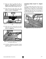
34. Slide the rip fence body assembly onto the
rip fence rail, then install the two handles and
one knob, as shown in
Figure 32.
You may have to adjust the rip fence rail hex
nuts on both sides so that the fence body
does not rub against the sides of the table
and extension wing.
32. Remove one hex nut, lock washer, and flat
washer from each of the fence rail mounting
studs.
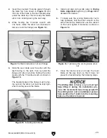
31. Attach the rip fence scale to the rear side
of the cast iron table and rear extension
wing with (3) M6-1 x 12 button head cap
screws and 6mm flat washers, as shown in
Figure 30.
Hand-tighten the cap screws for now—they
will be fully tightened in a later step.
Figure 30. Rip fence scale attached.
Rip Fence Scale
Figure 32. Rip fence body assembly installed.
Micro-Adjust
Lock Knob
Fence Clamp
Handle
Fence Lock
Handle
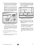
Figure 31. Rip fence rail installed.
Rip Fence
Rail
33. Install the rip fence rail by inserting the studs
into the provided holes in the cast iron table
and rear extension wing, as shown in
Figure
31, then secure them with the hex nuts,
lock washers, and flat washers removed in
Step 32.
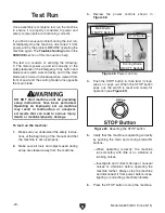
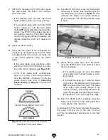
35. Remove the rip fence stop screw from the tall
side of the rip fence (see
Figure 33).
Figure 33. Rip fence stop screws.
Fence Stop
Screws
The rip fence stop screws keep the fence
from moving forward and slipping off the
fence body, which could draw your hands
and arms into the spinning blade during
operation. Always keep these stop screws
properly installed.
Содержание G0699
Страница 21: ...Model G0699 Mfd Since 5 15 19 5mm Hardware Recognition Chart...
Страница 108: ......