


Model G0699 (Mfd. Since 5/15)
-31-
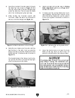
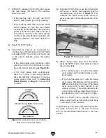
45. Back the rip fence away from the saw blade
at least
1
⁄
8
", then slide the fence rail stop
ring onto the rail and secure it against the
fence body by tightening the pre-installed set
screw, as shown in
Figure 39.
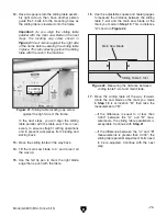
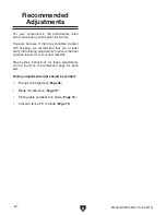
46. Attach the flat end cap to the other end of
the rail with the M8-1.25 x 16 cap screw and
8mm lock washer, as shown in
Figure 40.
Note: The purpose of the end cap is to pre-
vent the rip fence assembly from slipping off
the end of the rail.
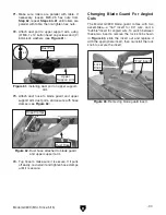
The scoring blade has wedge-shaped teeth
so that the higher the blade is raised, the
wider the scoring kerf will be.
The goal in the next step is to adjust the scor-
ing blade vertical and horizontal positions
so that the scoring kerf is the same width
as the main saw blade kerf. This procedure
requires placing the straightedge on both
sides of the blades multiple times as you
make adjustments.
47. When positioning the straightedge, place it
against teeth at both ends of the main saw
blade to obtain an accurate reading of the
main saw blade kerf.
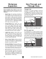
— Horizontal Adjustment: Insert the T-handle
wrench into the right hole shown in
Figure 41, engage it with the adjustment
bolt under the table, then rotate the wrench
to position the scoring blade.
Figure 39. Installing the rip fence stop ring.
Stop Ring
1
⁄
8
" Away
From Blade
Figure 40. Rip fence rail end cap attached.
End Cap
Figure 41. Adjusting the horizontal position of
the scoring blade.
Straightedge
Scoring Blade
Содержание G0699
Страница 21: ...Model G0699 Mfd Since 5 15 19 5mm Hardware Recognition Chart...
Страница 108: ......