


-26-
Model G0699 (Mfd. Since 5/15)
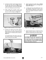
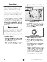
18. Loosen the jam nuts on the sliding table par-
allel bolts (see
Figure 23) that are on both
sides of the cabinet behind the sliding table,
then adjust the bolts in or out in small incre-
ments to change the sliding table parallelism
to the saw blade.
19. Make sure the sliding table is against the
adjustment bolts, then repeat
Steps 16–17
until the difference between the "A" and "B"
measurements is acceptable.
20. Re-tighten the jam nuts.
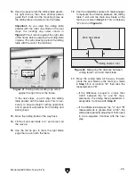
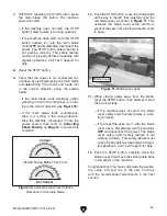
21. Remove the panels on both sides of the
frame to gain access to the forward and rear
sliding table T-bolts (see
Figure 24 for the
location of the forward access T-bolt).
Figure 23. Sliding table parallel adjustment bolt
(1 of 2).
Parallel Adjustment
Bolt & Jam Nut (1 of 2)
Figure 24. Location of the forward sliding table
T-bolt from the rear of the frame.
23. Make sure the sliding table is against both
parallel adjustment bolts and the locating cap
screw shown in
Figure 21 on Page 25, then
secure the sliding table with (3) M12-1.75
hex nuts, 12mm lock washers, and 12mm
flat washers. Replace the forward and rear
access panels.
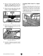
24. Install the sliding table push handle into the
front T-slot with a 12mm flat washer, 12mm
nylon flat washer, and a M12-1.75 T-nut, as
shown in
Figure 26.
22. Locate the middle sliding table T-bolt through
the 5" dust chute hole on the forward side of
the cabinet, as shown in
Figure 25.
Figure 26. Sliding table push handle installed.
Figure 25. Location of the middle sliding table
T-bolt.
Push Handle
Содержание G0699
Страница 21: ...Model G0699 Mfd Since 5 15 19 5mm Hardware Recognition Chart...
Страница 108: ......