


-74-
Model G0699 (Mfd. Since 5/15)
Adjusting Sliding
Table Parallelism
4. Move the sliding table all the way forward and
lock it in place.
5. Tilt the main blade all the way to the 45°
mark, then place the 45° square against the
blade and table.
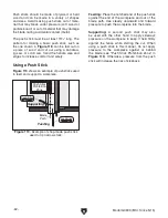
— If the blade is not 45° to the table, reach
through the gap between the main table
and sliding table base (see
Figure 142),
loosen the two set screws on the 45° stop
nut, then adjust the nut on the leadscrew
until you can move the blade to be 45° to
the main table. Re-tighten the set screws
on the stop nut.
To check and adjust the sliding table parallel-
ism:
1. DISCONNECT SAW FROM POWER!
2. Move the sliding table all the way back.
3. Move the main saw blade to 0° and raise it all
the way up.
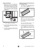
4. Use the felt tip pen to make a mark on the
right blade edge that is even with the table.
5. Use the adjustable square to measure the
distance from the sliding table T-slot and the
main saw blade at the mark you made in
Step
4. This is distance "A" shown in Figure 143.
A
B
Main Saw Blade
Sliding Table T-Slot
Figure 143. Measuring the distance between
sliding table T-slot and main blade.
If the cuts are not square when using the sliding
table, the table may not be parallel to the main
blade. Making sure that the sliding table is parallel
to the blade is necessary to ensure straight cut-
ting operations and to prevent the workpiece from
binding and kicking back.
Tools Needed
Qty
Felt Tip Pen ....................................................... 1
Adjustable Square ............................................. 1
Wrench 17mm.................................................... 1
Wrench 19mm ................................................... 1
Figure 142. Tilt leadscrew 45° stop nut (viewed
with main table removed for clarity).
45°
Stop Nut
Содержание G0699
Страница 21: ...Model G0699 Mfd Since 5 15 19 5mm Hardware Recognition Chart...
Страница 108: ......