


-30-
Model G0699 (Mfd. Since 5/15)
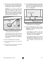
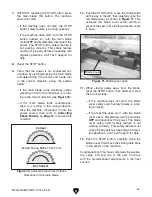
44. Move the rip fence up against the saw blade,
then position the rip fence scale so that the
zero mark is even with face of the rip fence,
as shown in
Figure 38.
Make sure the scale is even with the top sur-
faces of the table and extension wing, then
fully tighten the cap screws that secure the
scale in place.
Figure 38. Rip fence scale zero mark even with
the rip fence face.
Fence Scale
Zero Mark
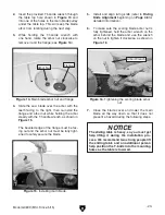
41. Check if the any part of the metal rip fence
body rests on the surface of the table.
— If the forward end of the fence body rests
on the table, lift the fence up so that you
can access the roller and acorn nut shown
in
Figure 37. Loosen the acorn nut, adjust
the roller until it extends slightly beyond the
body, then re-tighten the acorn nut.
— If the rear end of the fence body rests on
the table, adjust the height of the fence rail.
42. If you have not already fully tightened the
outer fence rail hex nuts in a previous step,
do so now.
43. Make sure the rip fence is still even with the
saw blade and the ride height is still correct.
If necessary, repeat previous steps to make
the rip fence position correct.
Figure 37. Rip fence body roller controls.
Roller
Acorn Nut
When properly positioned, the rail stop ring
prevents the rip fence from contacting the
saw blade. If this happens during cutting
operations, flying metal debris could cause
serious personal injury. Always make sure
the rail stop ring is secured in the proper
position before beginning operations.
Содержание G0699
Страница 21: ...Model G0699 Mfd Since 5 15 19 5mm Hardware Recognition Chart...
Страница 108: ......