


When you are finished installing the flying wires on the left
side of the model, repeat the process to make the flying
wires on the right side.
❏
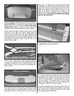
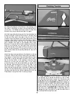
3. To make the flying wires for the tail surfaces start by
installing the 70-degree metal brackets. Note the locations
in the photograph above. Measure from the top of the fin to
a point 2" (51mm) down and 1/4" (6mm) forward from the
trailing edge of the fin and mark that location. Next,
measure from the outboard tip of each stab trailing edge to
a point 5" (127mm) inboard and 1/4" (6mm) forward from
the trailing edge of the horizontal stab and mark those
locations. In these three marked locations drill a 1/8" (3mm)
clearance hole through the fin and stabilizer. Saturate these
holes completely with thin CA.
At the bottom end of the fuselage, measure forward from the
tail post of the fuselage to a point 2-1/2" (64mm) and drill a
1/16" (1.6mm) hole at these locations on both sides of the
fuselage. Again, use the described procedure on page 8 to
install the brackets using two #4 x 1/2 " (13 mm) Phillips
head wood screws.
❏
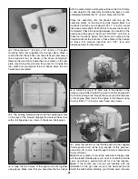
4. Locate three 4-40 x 5/8" (15.9 mm) Phillips Head
Machine Screws, three 4-40 stop nuts, and eight 70-degree
metal brackets as shown in the photograph. Mount six
brackets at the three drilled locations; two brackets are
placed on top of the stab and two under it. The proper
installation is shown in the photographs.
Note
: The fit of the 4-40 x 5/8" (15.9 mm) Phillips Head
Machine Screws into the bracket is a bit tight but will fit; you
may need to thread it into place.
❏
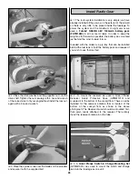
5. Notice that the brackets are mounted on the fin as
shown with the indicated "bend" at the top as shown in the
photograph above.
❏
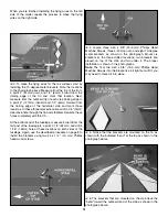
6. The brackets that are mounted on the stab have the
“bend” toward the outboard end of the stab as shown in the
photograph above.
31


