❏
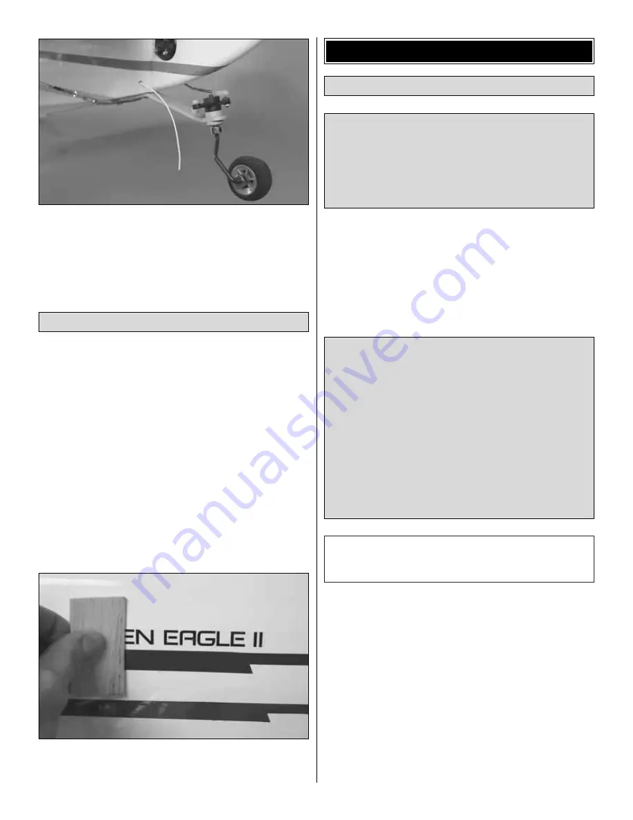
3. Route the receiver antenna down through the antenna
tube inside the fuselage. Drill a small hole in the back of the
fuselage for the antenna to exit. Use a small plastic pushrod
tube or a piece of wire to guide the antenna through the hole.
The decals may be cut from the sheet and applied directly
to the model, or they may be applied “wet” using the soap
and water method described below. Applying the decals with
soap and water allows for perfect positioning and eliminates
ugly air bubbles that can be trapped under the decal.
1. Use scissors or a sharp hobby knife to cut the decals from
the sheet.
2. Be certain the model is clean and free from oily
fingerprints and dust. Prepare a dishpan or small bucket with
a mixture of liquid dish soap and warm water—about one
teaspoon of soap per gallon of water. Peel the backing from
the decal while holding it under the solution.
3. Position the decal on the model where desired. Holding the
decal down, use a paper towel to wipe most of the water away.
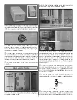
4. Use a piece of soft balsa or something similar to squeegee
remaining water from under the decal. Apply the rest of the
decals the same way.
At this stage the model should be in ready-to-fly condition
with all of the systems in place including the engine, landing
gear, wheels and pants and the complete radio system.
❏
1. If you have not already done so, accurately mark the
recommended C.G. location and the forward and aft C.G.
limits on the bottom of the top wing as described in step 1
on page 35 and below.
❏
2. With the wings attached to the fuselage, all parts of the
model installed (ready to fly) and an empty fuel tank, place
one fingertip from each hand on the recommended balance
point near both ends of the center panel and lift the model.
❏
3. If the tail drops, the model is “tail heavy” and the battery
pack and/or receiver must be shifted forward or weight must
be added to the nose to balance. If the nose drops, the model
is “nose heavy” and the battery pack and/or receiver must be
shifted aft or weight must be added to the tail to balance.
Usually, it is desirable to relocate the battery pack and
receiver to minimize or eliminate any additional ballast
required. But if only minimal weight is required to achieve the
correct balance, a few extra ounces of ballast will not be
noticed with a model of this size. If additional weight is
When balancing a larger model such as this it is helpful to
have an assistant. One person can lift the model and the other
can view it from the side to determine whether or not it is level.
The recommended C.G. for the Christen Eagle II ARF is
6-1/8" [156mm] back from the leading edge of the center
section of the top wing. Your model should be balanced at
the recommended C.G. location for the first flights. Later,
you may wish to experiment by shifting the C.G. up to 3/4"
[19mm] forward or 3/4" [19mm] back to change the flying
characteristics. Moving the C.G. forward may improve the
smoothness and stability, but the model may then require
more speed for takeoff and make it more difficult to slow for
landing. Moving the C.G. aft makes the model more
maneuverable, but could also cause it to become more
difficult to control. In any case, start at the recommended
balance point and do not at any time balance the model
outside the specified range.
More than any other factor, the C.G. (balance point) can
have the greatest effect on how a model flies and may
determine whether or not your first flight will be
successful. If you value this model and wish to enjoy it for
many flights, DO NOT OVERLOOK THIS IMPORTANT
PROCEDURE. A model that is not properly balanced will
be unstable and possibly unflyable.
Balance the Model (C.G.)
GET THE MODEL READY TO FLY
Apply the Decals
42


