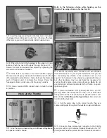
❏
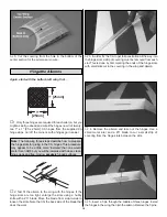
5. Cut or drill clearance holes in the firewall for the heads
of the bolts that hold the engine to the mount plate, then
mount the plate to the firewall with four more 1/4-20 x 3/4"
[19mm] bolts, washers and 1/4-20 blind nuts included with
this kit. When mounted to the engine, the backplate of the
spinner should be 6-1/2" [165mm] from the firewall.
❏
6. Pin the firewall to the fuselage by performing steps
6 and 7.
MOUNTING A FUJI BT-50SB GAS ENGINE
These instructions show how to mount a Fuji BT-50SB engine.
The prop hub that comes with the engine must be exchanged
for a Fuji short prop hub (FJIG6754—sold separately). If
mounting a different gas engine, these instructions may be
used as a guide. The Fuji 50 with the short prop hub will
automatically have the correct spacing from the firewall, but if
mounting another engine, the back plate of the spinner should
be 6-1/2" [165mm] from the firewall.
❏
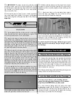
1. Use a straightedge and a pen to extend the horizontal and
vertical centerlines on the firewall all the way to the edges.
❏
2. Cut the Fuji BT-50 engine mounting bolt pattern from
page 49. (If making a photo copy, be certain it comes out the
same size as the pattern and is not dimensionally distorted.)
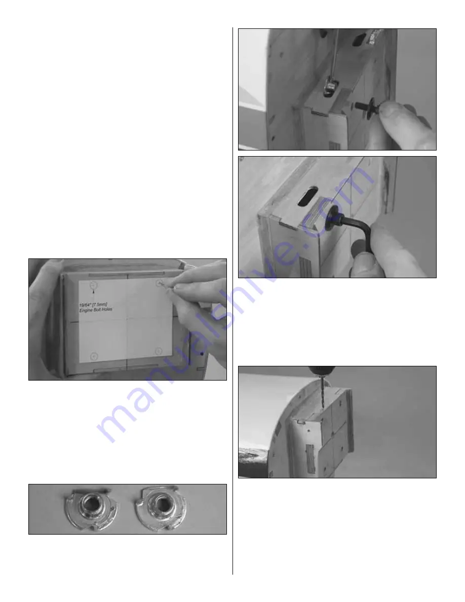
Tape the pattern to the firewall aligning the lines on the pattern
with the lines on the firewall. Use a large T-pin to mark the
center of the engine mounting holes onto the firewall.
❏
3. Remove the pattern from the firewall. Drill 1/16"
[1.6mm] pilot holes at the marks. Enlarge the holes with a
19/64" [7.6mm] drill.
❏
4. Use large wire cutters, a metal file or a rotary tool with
a cutoff wheel to trim two 1/4-20 blind nuts so they will fit in
the top holes in the firewall without interfering with the top of
the engine box.
❏
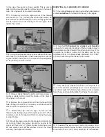
5. Apply a few dabs of epoxy to the flange of one of the
blind nuts. Use hemostats or needle nose pliers to hold the
nut to the back of the firewall while threading a 1/4-20 x 1"
[25mm] socket head cap screw (not included) with a large
1/4" [6.4mm] washer to the nut. Use a 3/16" [4.8mm] hex
wrench to tighten the screw fully, drawing the nut into the
back of the firewall. Install the remaining three blind nuts the
same way.
❏
6. Drill 1/8" [3.2mm] holes 3/4" [20mm] deep through the
top, bottom and both sides of the “box” that holds the
firewall. The holes should be centered over the sides of the
firewall and there should be at least two holes per side.
❏
7. Cut one of the supplied 1/8" x 10" [3.2 x 250mm] wood
dowels into as many 3/4" [20mm] pieces as holes were
drilled around the firewall. Use epoxy to glue the dowels into
the holes. Cut or sand the ends of the dowels even with the
engine box sides.
19


